Urban road lamp energy saving control and management system based on WSN

A technology of energy-saving control and management system, applied in energy-saving control technology, energy-saving lighting, energy-saving ICT and other directions, can solve the problems such as the inability to truly realize the time-sharing on-demand lighting mode, the inability to realize the dimming control of street lamps, and the inability to control a single street lamp. , to achieve the effect of convenient control, convenient installation, and reduced investment in transformation

Inactive Publication Date: 2009-04-29
王雷
View PDF0 Cites 10 Cited by
  • Summary
  • Abstract
  • Description
  • Claims
  • Application Information

AI Technical Summary

Problems solved by technology

[0002] The traditional street light controller can only realize the control of one line, that is, it can only realize the line control, and cannot control a single street light. When wiring, the wires are routed separately, which is very unfavorable for the energy-saving transformation of the existing street lighting system
The existing street lamp control system is to place a control device and a GPRS (General Packet Radio Service) communication module at the position of each street lamp transformer. Dimming control of street lights
It is impossible to truly realize the on-demand lighting mode of "time-by-time, road-section, and scene-by-scenario"

Method used


Image

  • Urban road lamp energy saving control and management system based on WSN
  • Urban road lamp energy saving control and management system based on WSN
  • Urban road lamp energy saving control and management system based on WSN

Examples


Embodiment Construction

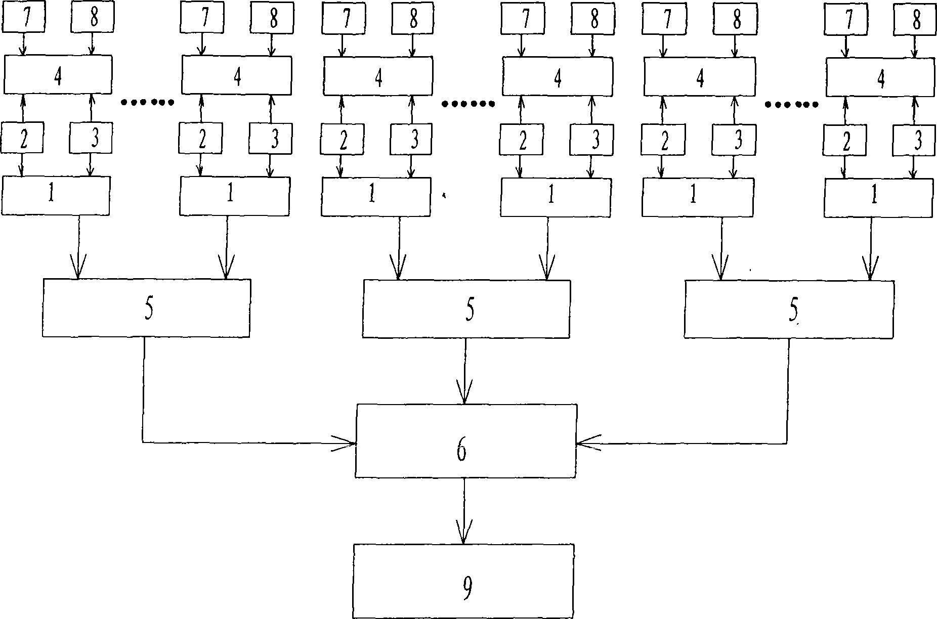
[0017] Such as figure 1 As shown, the energy-saving street lamp control system of the present invention includes a node module 1, a control module 4 and a coordinator 5, each street lamp is equipped with a node module 1 and a control module 4, and the node module 1 includes a radio frequency module 2 and a microprocessor ( CPU) 3, radio frequency module 2 and microprocessor 3 are all connected on the control module 4 by the mode of inserting pin. Each node module communicates with the coordinator 5 in a wireless relay manner, and the control module 4 includes a transformer 7 and a relay 8 . Each node module on a street lamp in an area communicates with a coordinator 5 in a wireless relay manner, and each coordinator communicates with a general RTU (remote terminal control system) 9 through a GPRS communication module 6 .

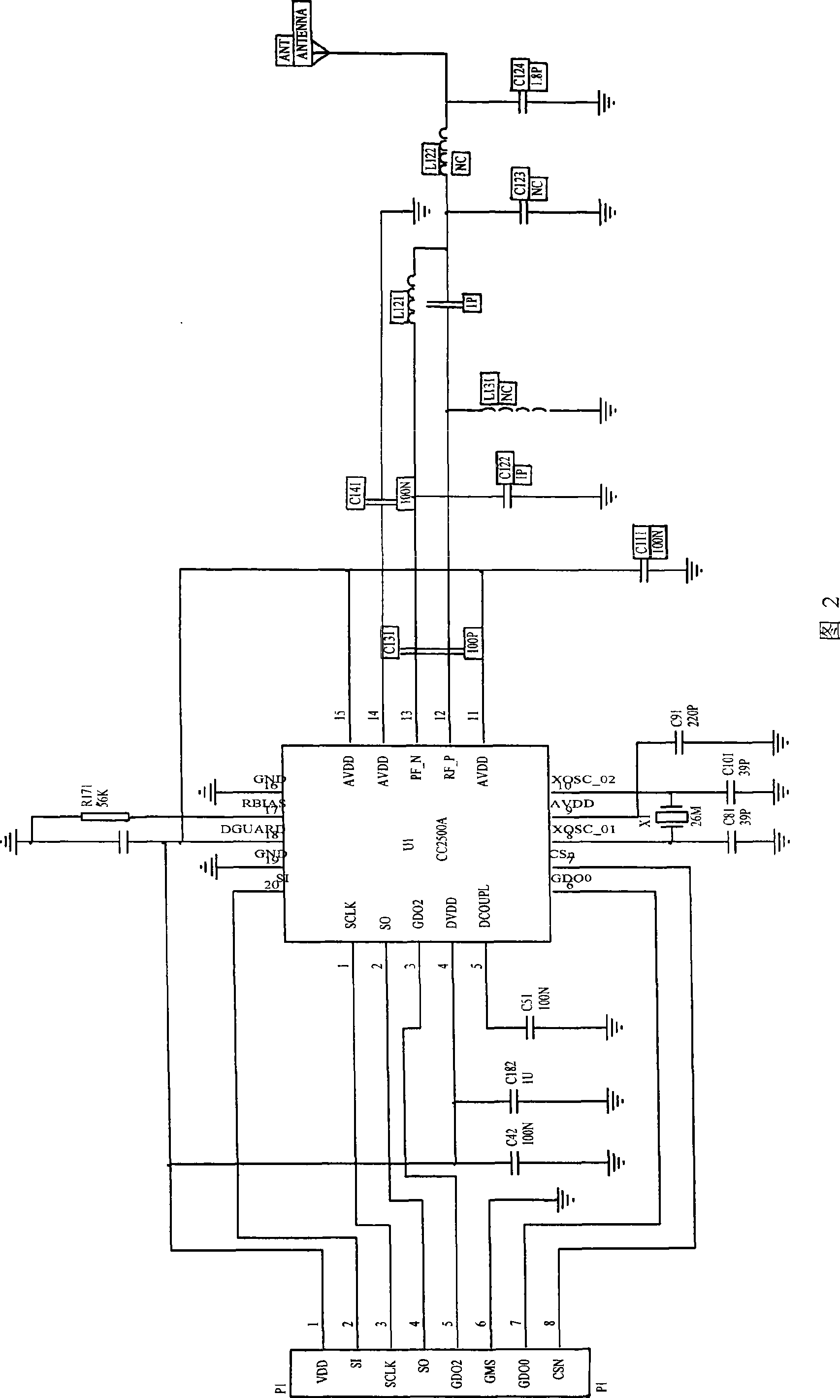
[0018] The circuit principle of the radio frequency module 2 is shown in FIG. 2 , which uses the 2.4GHz ISM (industrial, scientific, medical) license-free ...


PUM


Abstract

The invention provides a WSN-based urban street light energy-saving control and management system. The system comprises node modules, control modules and coordinators, one node module and one control module are arranged on each street light, each node module comprises a radio frequency module and a microprocessor, the radio frequency module and the microprocessor are connected on the control module by plugging pins in, the various node modules on the street lights and one coordinate in a region adopt the wireless relay mode for communication and connection, each control module comprises a transformer and a relay and is provided with two output control circuits, one circuit controls the switch amount of lighting of a secondary road, the other circuit is the dimming output for controlling the dimming of a main road, and all the coordinators are communicated and connected by a GPRS and a universal RTU. The system has convenient control implementation and can effectively reduce the energy consumption of the street lights, realize the initiative alarm of street light faults and street light aging and effectively reduce the workload of patrol officers of the street lights, has small size and can greatly facilitate the installation of working staff.

Description

technical field [0001] The invention relates to a street lamp energy-saving control system, belonging to the technical field of urban street lamp energy-saving. Background technique [0002] The traditional street light controller can only realize the control of one line, that is, it can only realize the line control, and cannot control a single street light. When wiring, wires are routed separately, which is very unfavorable for energy-saving transformation of existing street lighting systems. The existing street lamp control system is to place a control device and a GPRS (General Packet Radio Service) communication module at the position of each street lamp transformer. Dimming control of street lamps. It is impossible to truly realize the on-demand lighting mode of "time-by-time, road-section, and scene-by-scenario". [0003] On the other hand, with the rapid development of Micro-Electro-Mechanical System (Micro-Electro-Mechanism System, MEMS), System on Chip (SOC, Sys...

Claims


Application Information

Patent Timeline
Patent Type & Authority Applications(China)
IPC IPC(8): H05B37/02F21V23/00G08C17/02F21W131/103
CPCY02B20/40Y02B60/50Y02B20/72
Inventor 杜晓通王雷艾茂良
Owner 王雷
Why Eureka
Try Eureka