Impact drill

A technology of impact drill and casing, applied in the directions of portable impact tools, striking tools, portable drilling rigs, etc., can solve the problem of large axial size of impact drills

Active Publication Date: 2009-05-06
POSITEC MACHINERY ZHANGJIAGANG +1
View PDF1 Cites 11 Cited by
  • Summary
  • Abstract
  • Description
  • Claims
  • Application Information

AI Technical Summary

Problems solved by technology

This arrangement of the hammer drill, because a cam ring is added in the axial di

Method used


Image

  • Impact drill
  • Impact drill
  • Impact drill

Examples


Embodiment Construction

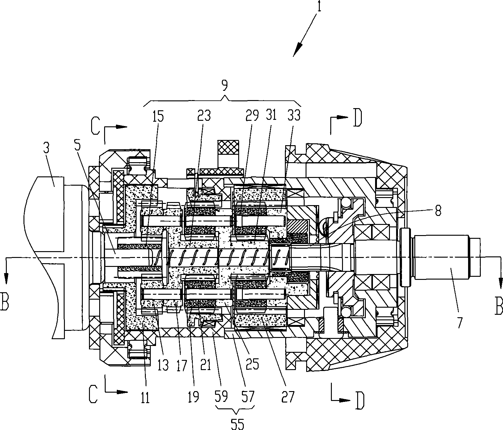
[0024] refer to Figure 1 to Figure 2 , a three-function impact drill 1, can be operated in one of three modes of screwdriver, drilling and impact. The three-function hammer drill 1 includes a motor 3 having a rotating motor output shaft 5 for transmitting the rotational motion of the motor 3 to a spindle 7 . The main shaft 7 is located at the front end of the hammer drill 1 for driving the working head (not shown), and the rear end of the main shaft 7 is provided with an external spline 8 . A gear reduction mechanism 9 is provided between the motor 3 and the main shaft 7 , and the reduction gear mechanism 9 is used to reduce the higher rotational speed of the output shaft 5 of the motor and then transmit it to the main shaft 7 .

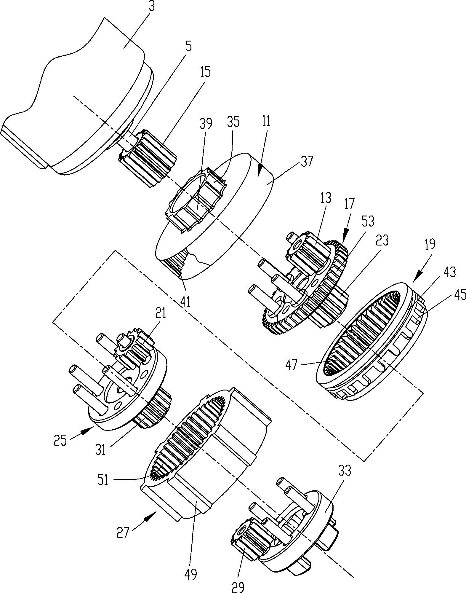
[0025] The gear reduction mechanism 9 includes a three-stage planetary gear set, the first-stage planetary gear set includes a first ring gear 11, the first planetary gear 13 meshes with the first ring gear 11, and the first sun gear 15 meshes with...


PUM


Abstract

The invention provides a percussion drill which comprises a casing, a main shaft, a still end tooth which is installed inside the casing and can not rotate relatively to the casting, a movable end tooth which is fixedly connected on the main shaft and can move along with the main shaft, and a function shifting mechanism used for leading the movable end tooth and the still end tooth to be engaged optionally. The function shifting mechanism comprises a restraining element which is matched with the movable end tooth movably along the radial direction so as to prevent the movable end tooth from axial movement.

Description

technical field [0001] The invention relates to an impact electric tool, in particular to a function switching mechanism of the impact electric tool. Background technique [0002] U.S. Patent No. 5,458,206 discloses a percussion drill. The percussion drill includes a main shaft, a movable end tooth fixedly connected to the main shaft and capable of moving axially with the main shaft, and a static end tooth connected to the casing, which cannot rotate relative to the casing. However, it can move in a small range in the axial direction. A cam ring is located at the rear end of the static end teeth. A groove is provided on the end surface of the cam ring opposite to the static end teeth, and the end surface of the stationary end teeth is opposite to the cam ring. There is a protrusion on the top. When the groove and the protrusion are matched, the static end teeth and the movable end teeth cannot be meshed, and the impact drill cannot produce impact action. By rotating the cam...

Claims


Application Information

Patent Timeline
IPC IPC(8): B25F3/00B25D16/00B23B45/16B25B21/00B25B23/14
Inventor 何明明张伟
Owner POSITEC MACHINERY ZHANGJIAGANG
Why Eureka
Try Eureka