Heavy-load electric wheel

An electric wheel and spoke technology, applied in electric components, wheels, brakes, etc., can solve problems such as poor reliability of brakes, poor motor stiffness, and failure of rotating seals, and achieve slow friction plate loss, reasonable bearing relationship, and short axial dimensions. Effect

Pending Publication Date: 2020-07-03
南京清研易为新能源动力有限责任公司
View PDF0 Cites 7 Cited by
  • Summary
  • Abstract
  • Description
  • Claims
  • Application Information

AI Technical Summary

Problems solved by technology

[0006] In the existing deceleration drive electric wheel technology, a common solution is to arrange the hub bearing between the motor housing and the output end of the reducer, such as the invention patent of Chinese patent application No. 2017107496209 "An Electric Wheel The force transmission method and the vehicle using the method", the invention patent of Chinese patent application No. In the disclosure of the drive unit, the output end of the reducer is equivalent to the hub of the traditional wheel. This arrangement makes the structure of the motor housing and the output end of the reducer more complicated, and increases the cost of the electric wheel.
Moreover, on the one hand, this structure makes the housing of the motor not only bear the torque of the wheel, but also bear the vertical load of the wheel from the hub bearing, and is in a state of combined bending and torsion stress, and the stress condition is relatively harsh, which may Problems leading to poor stiffness of the motor, which in turn affects its reliability
On the other hand, this structure often arranges the brake between the reducer and the hub motor (that is, the invention patent with the Chinese patent application No. 2017106143197 and the invention patent with the Chinese patent application No. The motor, brake, and reducer are arranged in sequence at the far end, resulting in poor heat dissipation conditions for the brake. When braking, the local temperature of the brake can be as high as hundreds of degrees Celsius. The temperature is too high, which will lead to problems such as demagnetization of permanent magnets and failure of rotating seals
[0007] A common solution is to drive the electric wheel by deceleration, such as the invention patent of Chinese patent application No. 2018112345985 "A hub motor drive axle with built-in reduction mechanism", and the invention patent of Chinese patent application No. 201810454446X "A low-floor electric axle Assemblies" and the Chinese patent application number 2019101670982 "An Electric Wheel Assembly Using Drum Brakes" disclose that the reducer is arranged at the high-speed end of the electric wheel, that is, the brake disc is connected to the shaft of the motor, The electric wheel is sequentially composed of brakes, hub motors and reducers from the axial proximal end to the distal end. This arrangement is conducive to the heat dissipation of the brakes. However, due to the high speed of the brake disc, the wear of the brake friction plates is relatively fast, and the brakes are reliable. Poor sex

Method used


Image

  • Heavy-load electric wheel
  • Heavy-load electric wheel
  • Heavy-load electric wheel

Examples


Embodiment 1

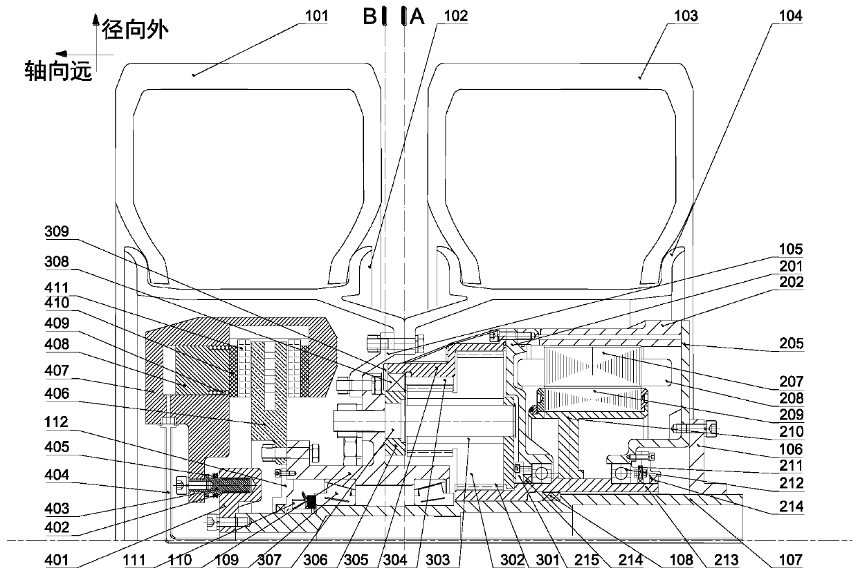
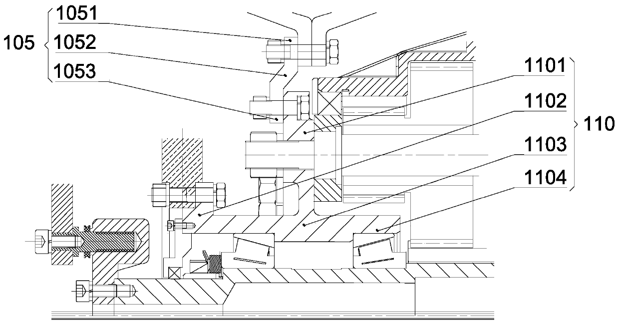
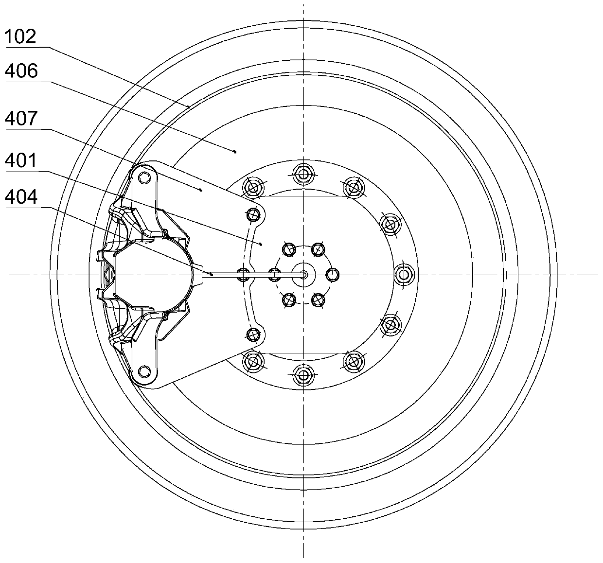
[0046] Such as Figure 1 ~ Figure 5 with Picture 10 The shown embodiment 1 of the present invention includes: wheel support shaft 107, spokes 105, rim 115, hub motor, planetary gear reducer and brake; wherein the brake, planetary gear reducer and hub motor are arranged on the support shaft in order from far to near The outer side of 107, the outer side of the hub 110 is connected with the spoke installation plane of the rim through the spoke 105, the hub 110 is mounted on the outer side of the support shaft 107 through a pair of hub bearings 109; the caliper bracket 401 in the brake is mounted on the wheel support shaft by bolts Outside the distal end of 107, the brake disc 406 is installed on the brake disc mounting flange of the hub 110; the hub part of the hub motor rotor support 210 is sheathed on the rotor shaft 213; the sun gear 301 in the planetary gear reducer is arranged on the rotor Outside the distal end of the shaft 213, the outer end of the planet pin 307 in the p...


PUM


Abstract

The invention discloses a heavy-load electric wheel, and belongs to the field of electric vehicle power devices. A brake, a planetary gear reducer and a hub motor are sequentially arranged on the outer side of a supporting shaft from the distant to the near; the outer side of a hub is connected with a spoke mounting plane of a rim through a spoke, and the hub is mounted on the outer side of the supporting shaft through a pair of hub bearings; a brake caliper support in the brake is installed outside the distal facet of the wheel supporting shaft through a bolt, and a brake disc is installed ona brake disc installation flange of the hub; a hub part of the hub motor rotor support is sleeved on the rotor shaft; and a sun gear in the planetary gear reducer is disposed outside the distal end side of the rotor shaft. The axial size of the whole electric wheel assembly is short, and the hub motor, the planetary gear reducer and the brake are all arranged in the space defined by the rim on the inner side and the outer side of the electric wheel assembly, so that the electric wheel assembly can be suitable for common commercial vehicle double-tire parallel loading wheels.

Description

Technical field [0001] The invention belongs to the technical field of electric vehicle power devices, and is specifically a heavy-duty electric wheel. Background technique [0002] Traditional commercial vehicles generally use a centralized drive method, and their performance improvement is often limited in many aspects, such as: the transmission chain is long, requiring components such as transmission shaft, transfer case and differential, which affects the general layout and lightweight , The overall low efficiency of the transmission system limits the number of drive axles, thereby restricting the development of vehicles in the direction of super long and heavy loads; a single engine provides power, and the power transmission is a series transmission method, resulting in poor reliability and fault tolerance ; Low specific power and limited power. Therefore, the development of high-power engine technology has become a bottleneck for technological progress. For new energy com...

Claims


Application Information

Patent Timeline
Patent Type & Authority Applications(China)
IPC IPC(8): B60B35/12B60K7/00B60T1/06B60K17/12B60R17/00H02K7/00H02K7/116H02K1/30H02K5/04H02K9/00H02K9/19
CPCB60B35/125B60K7/0007B60K17/12B60R17/00B60T1/065H02K1/30H02K5/04H02K7/006H02K7/116H02K9/00H02K9/19
Inventor 李建秋胡家毅刘树成蔡炳坤李航李园园宋金鹏李景康欧阳明高徐梁飞胡尊严
Owner 南京清研易为新能源动力有限责任公司
Why Eureka
Try Eureka