Multi-clutch module, clutch oil supply system and electric control hydraulic automatic transmission

A multi-clutch, clutch technology, applied in clutches, fluid-driven clutches, non-mechanical-driven clutches, etc., can solve the problems of difficulty in realization, high cost, and difficulty in structural arrangement and process realization of the oil supply system.

Active Publication Date: 2018-07-13
GUANGZHOU AUTOMOBILE GROUP CO LTD
View PDF16 Cites 9 Cited by
  • Summary
  • Abstract
  • Description
  • Claims
  • Application Information

AI Technical Summary

Problems solved by technology

However, as the number of gears increases, the number of clutches, brakes, and planetary rows also increases, and it is even more difficult to achieve a design that satisfies the theoretical stage ratio.
In traditional technology, wet clutches and brakes of electronically controlled hydraulic automatic transmissions generally use splines between the clutch hub and steel plates or friction plates to transmit torque and speed. Wet clutches and brakes have certain requirements for space layout. For automatic transmissions with multiple clutch assemblies and brakes, the overall space requirements are increased, and the clutch system is relatively complex, with high assembly requirements and high costs
In addition, automatic transmissions with multiple clutch assemblies and brakes also require multiple oil passages to provide oil, which increases the difficulty of structural layout and process realization of the oil supply system, and increases manufacturing costs, etc.

Method used


Image

  • Multi-clutch module, clutch oil supply system and electric control hydraulic automatic transmission
  • Multi-clutch module, clutch oil supply system and electric control hydraulic automatic transmission
  • Multi-clutch module, clutch oil supply system and electric control hydraulic automatic transmission

Examples


Embodiment Construction

[0072] Embodiments of the present invention are described in detail below, examples of which are illustrated in the accompanying drawings, wherein like numerals designate like parts throughout the drawings. The embodiments described below by referring to the figures are exemplary only for explaining the present invention and are not construed as limiting the present invention.

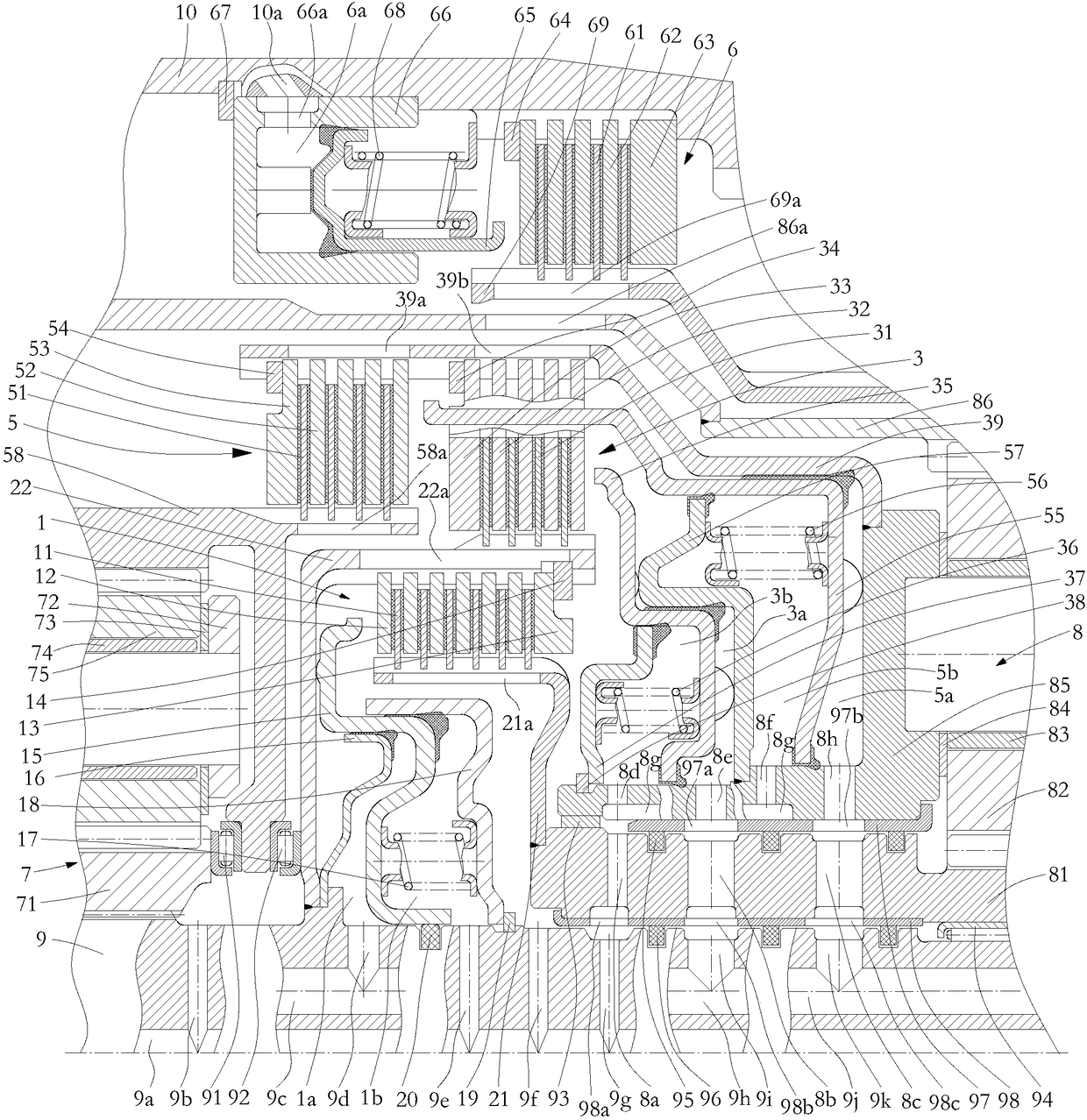
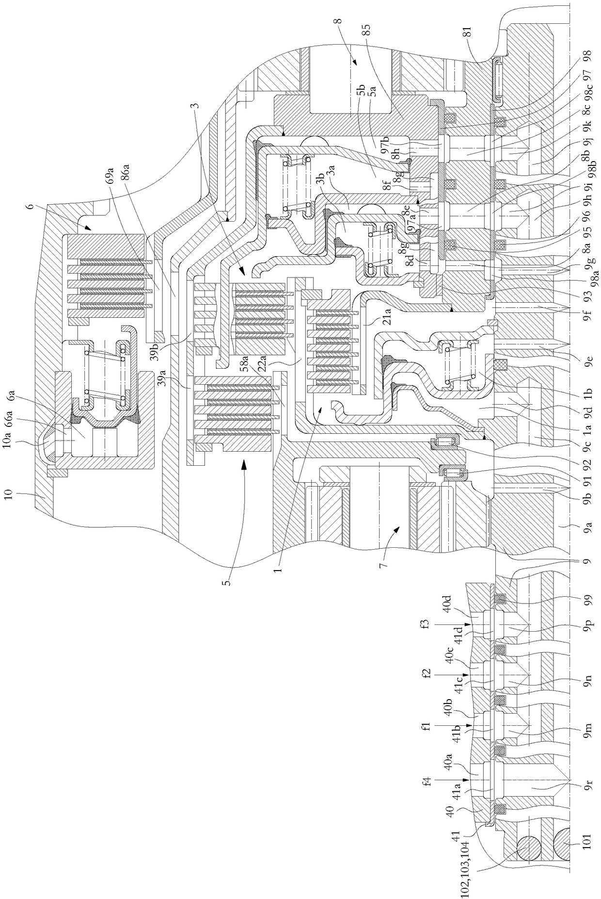
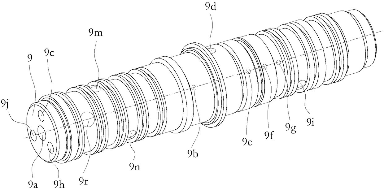
[0073] Such as figure 1 As shown, the present invention proposes a multi-clutch module, including a housing structure 10, an input shaft 9 disposed in the housing structure 10, a first planetary row structure 7, a second planetary row structure 8, and a first clutch structure 1 , the second clutch structure 3, the third clutch structure 5 and the brake structure 6. The above-mentioned multi-clutch module composed of multiple clutch structures, brake structures and planetary row structures can realize the switching of different gears through the engagement and separation of different clutch structures....


PUM


Abstract

The invention provides a multi-clutch module, a clutch oil supply system and an electric control hydraulic automatic transmission. The multi-clutch module comprises a shell structure, and an input shaft, a first planet row structure, a second planet row structure, a first clutch structure, a second clutch structure, a third clutch structure and a brake structure arranged in the shell structure; the first planet row structure and the second planet row structure are arranged at the two ends of the input shaft; the first clutch structure is connected to the second planet row structure and the input shaft; the second clutch structure is connected to the second planet row structure and the input shaft; the third clutch structure is connected to the first planet row structure and the input shaft; the brake structure is connected to the second planet row structure and the shell structure; the first clutch structure is positioned on the radial outer side of the input shaft; the second clutch structure and the third clutch structure are positioned on the outer side of the first clutch structure side by side; and the brake structure is positioned on the outer sides of the second clutch structure and the third clutch structure. The multi-clutch module is more compact in structure, reduces occupied space, simplifies the structure, and reduces the assembly requirements.

Description

technical field [0001] The invention relates to the technical field of automobile transmissions, in particular to a multi-clutch module, a clutch oil supply system and an electronically controlled hydraulic automatic transmission. Background technique [0002] The electronically controlled hydraulic automatic transmission (AT) is formed by adding an electronic control system on the basis of the traditional hydraulic automatic transmission. It can select the optimal speed ratio for different loads and vehicle speeds, so that the engine can work at the corresponding optimal speed. All gear changes are completed by the transmission itself, and the driver only uses the accelerator pedal to express the intention of changing the vehicle speed and selects the required operating state through the gear selector. This electronically controlled hydraulic automatic transmission generally realizes gear shifting through a planetary gear transmission mechanism including multiple clutches, ...

Claims


Application Information

Patent Timeline
Patent Type & Authority Applications(China)
IPC IPC(8): F16H3/44F16H57/04F16D25/10F16D25/0638F16D25/12
CPCF16D25/0638F16D25/10F16D25/12F16D25/14F16H3/44F16H57/0424F16H57/0473F16H2003/445F16H2200/2041F16H2200/2007
Inventor 张新桂余子林周友谢绪秒刘学武刘维
Owner GUANGZHOU AUTOMOBILE GROUP CO LTD
Why Eureka
Try Eureka