
Fully contained retention pin for a turbine nozzle

A turbine nozzle and retaining pin technology, applied in machine/engine, bolt, stator, etc., can solve problems such as increased nozzle structure cost, poor chord hinge seal, poor thermal insulation of retaining ring, etc.

Inactive Publication Date: 2009-05-06
GENERAL ELECTRIC CO
View PDF0 Cites 8 Cited by
  • Summary
  • Abstract
  • Description
  • Claims
  • Application Information

AI Technical Summary

Problems solved by technology

This variation results in more deterministic nozzle loading and better nozzle sealing, but also results in poorer insulation of the retaining ring, significantly increasing the cost of the nozzle construction
Some of the problems with hook retaining designs in the art include poor chordal hinge sealing, out of round retaining rings and high rear edge stress

Method used


Image

  • Fully contained retention pin for a turbine nozzle
  • Fully contained retention pin for a turbine nozzle
  • Fully contained retention pin for a turbine nozzle

Examples


Embodiment Construction

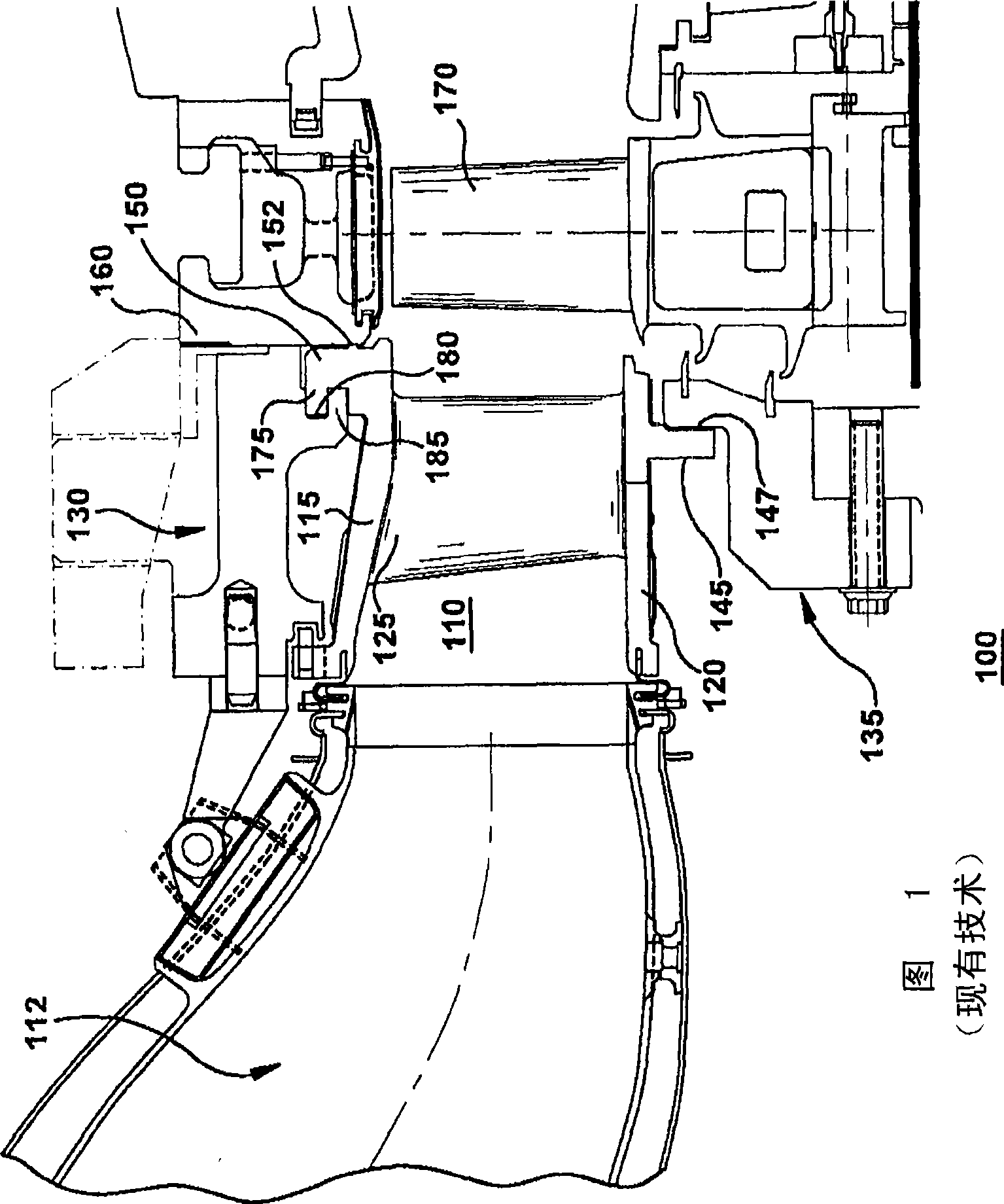
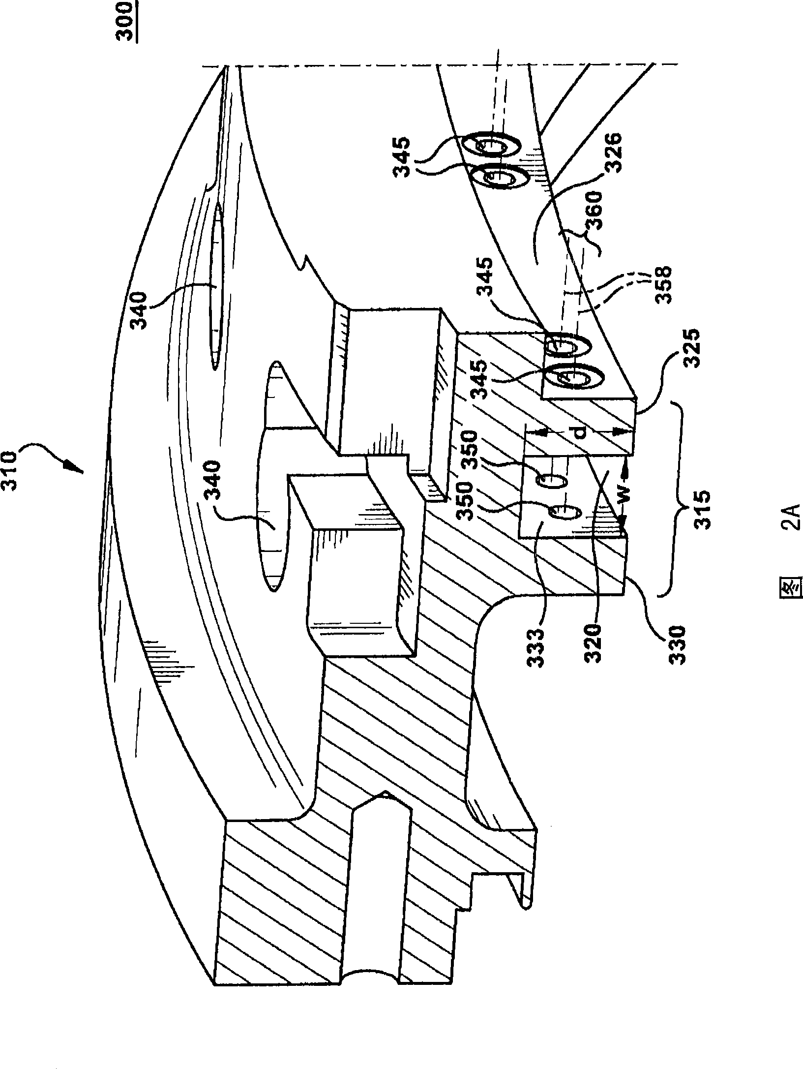
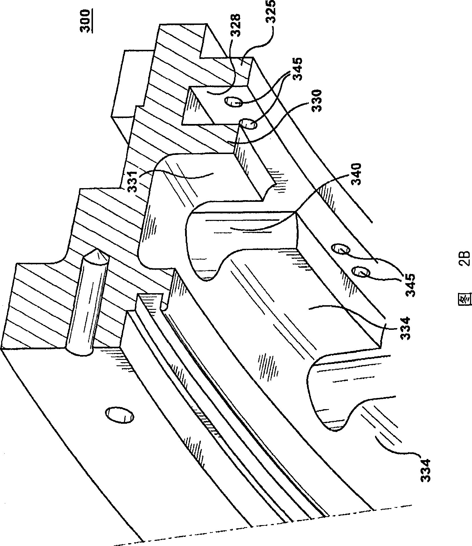
[0109] The following embodiments of the invention have several advantages, including improved nozzle stability, defined nozzle loading and provided retaining ring insulation. The pins are unique in the relative size and retention scheme of the features and are critical to the function of the turbine assembly (2 per nozzle). A pin for each nozzle will fix the radial and circumferential position of the nozzle, yet allow transitional motion. They also keep the nozzle and retaining ring in minimal contact so as to significantly reduce heat conduction from the nozzle to the retaining ring (a source of out-of-round retaining ring). By positioning the nozzles, they will also set the nozzle throat area desired for optimum turbine performance. The axial length of the pin is optimized so that it is impossible for the nozzle to disengage within the assembly due to the pin withdrawing from its normal axial position, and the pin is designed so that the pin will not fail due to low cycle f...


PUM


Abstract

A retention pin for fastening retaining lugs of an outer sidewall, of a turbine nozzle, within a groove between a forward land and an aft land of a retaining ring. The retention pins fit through coaxial holes in the lug and the lands, securing the radial and circumferential location of the nozzles as well as allowing transitional motion. While maintaining limited contact with both the nozzles andthe retaining ring they significantly reduce conductive heat transfer from the nozzle to the retaining ring. By positioning the nozzles, they also set the desired nozzle throat areas for targeted turbine performance. The pins have been designed such that the nozzle cannot disengage within the assembly due to the pin backing out of its nominal axial position, and the pin will not fail due to low cycle fatigue, creep, or yielding, all of which prevent nozzle fallout.

Description

technical field [0001] The present invention relates generally to a retention pin for a gas turbine nozzle, and more particularly to a fully contained retention pin for an outer sidewall retention scheme of a nozzle. Background technique [0002] In a gas turbine, hot combustion gases flow from the combustor through the nozzles and buckets of the first stage, and through the nozzles and buckets of the next turbine stage. The first stage nozzle typically includes an annular array or subassembly of cast nozzle segments, each of which includes one or more nozzle stator vanes per segment. Each first stage nozzle segment also includes inner and outer wall portions radially spaced from each other. When the nozzle segment is assembled, the stator vanes are circumferentially spaced from one another so as to form an annular array between the annular inner sidewall and the outer sidewall. A nozzle retainer ring coupled to the outer sidewall of the first stage nozzle supports the fir...

Claims


Application Information

Patent Timeline
Patent Type & Authority Applications(China)
IPC IPC(8): F16B19/02F01D9/02
CPCF05D2250/231F05B2250/231F01D9/042F16B19/02F05B2260/301Y10T403/75Y10T29/49323
Inventor A·K·哈特E·D·本杰明D·D·斯努克
Owner GENERAL ELECTRIC CO
Learn More