Method and unit for the extremely fine dispersal and discharge of an irritant or warfare agent

A technology of stimulants and combat agents, applied in the direction of injection devices, liquid injection devices, gas injection devices, etc., can solve the problem of reducing the discharge energy

Inactive Publication Date: 2009-05-06
卡尔-海因茨·德雷格
View PDF4 Cites 2 Cited by
  • Summary
  • Abstract
  • Description
  • Claims
  • Application Information

AI Technical Summary

Problems solved by technology

Not only does the plugged-in throttling cause this pro

Method used


Image

  • Method and unit for the extremely fine dispersal and discharge of an irritant or warfare agent

Examples


Embodiment Construction

[0027] Will compare with figure 1 Preferred embodiments of the present invention will be described in detail.

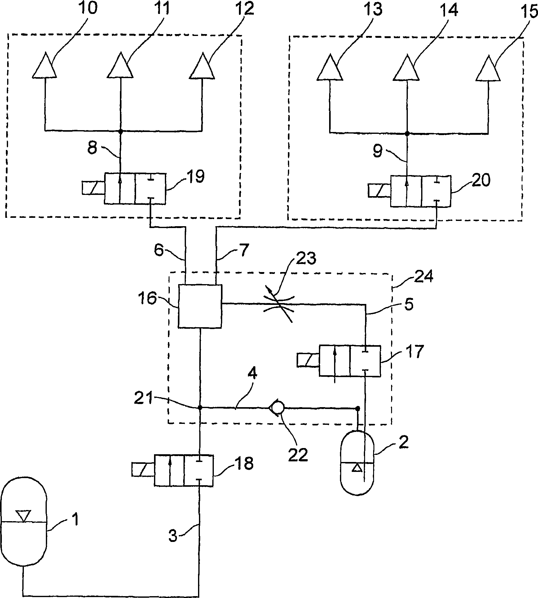
[0028] figure 1 The shown block diagram shows a stimulating agent or combat agent distribution device, wherein the stimulating agent or combat agent is delivered from the storage container 2 to a plurality of injectors via a branched pipeline system 3, 4, 5, 6, 7, 8, 9 Nozzles 10 to 15. In this exemplary embodiment, two sets of injection nozzles 10 , 11 , 12 and 13 , 14 , 15 are provided. These groups can be activated selectively via the 2 / 2-way valves 19 , 20 .

[0029] Through the 2 / 2 reversing valve 18 , the liquid booster gas is pressed from the liquefied gas bottle 1 into the pipeline 3 and delivered to the mixer 16 . At the inlet of the mixer 16 , at a branch point 21 , a part of the booster gas is branched off from the line 3 via the line 4 with a non-return valve 22 for the pressure build-up in the stimulant container 2 . The non-return valve 22 serves t...


PUM


Abstract

Method and unit for the dispersal and discharge of an irritant or warfare agent. With the invention, solid and liquid warfare agents and irritants are sprayed in large indoor and outdoor areas by means of a propellant gas (1) via a system of lines (3 to 9). The substances are transported in liquid form in liquefied gas solutions, or liquid gas emulsions, to their outlet openings (10 to 15) and emerge with the kinetic energy of a liquid, in order to disperse the irritant or warfare agent extremely finely by evaporation and the accompanying expansion of the liquefied gas.

Description

[0001] The invention relates to a method and a device for finely distributing solid and liquid combat or stimulant agents via a system of pipes in large indoor or outdoor areas for the defense of persons. Background technique [0002] Known stimulant and combat agent spraying devices use a booster gas, for example a propane / butane mixture, or the booster gas R 134 A known from nebulizers, in order to press the stimulant and combat agent out of the storage container. [0003] During this process, the booster gas evaporates and is discharged in the immediate vicinity of the storage container or is conducted as gas to the outlet. [0004] The discharge at the storage container only allows a limited spray range due to the spray distance of each storage container. As far as the subsequent lines are concerned, the booster gas draws energy from the storage container and the valves and lines for its evaporation and heating, so that there can only be short release intervals in order to...

Claims


Application Information

Patent Timeline
IPC IPC(8): B05B1/14F41H9/04B05B7/26
CPCF41H9/04B05B7/26B05B1/14B05B7/267
Inventor 卡尔-海因茨·德雷格
Owner 卡尔-海因茨·德雷格
Why Eureka
Try Eureka