
Method for fabrication of a structural element for aeronautical construction including a differential work hardening

一种结构元件、热加工的技术,应用在航空工程领域,能够解决无法转化等问题

Active Publication Date: 2009-05-06
CONSTELLIUM ISSOIRE
View PDF7 Cites 12 Cited by
  • Summary
  • Abstract
  • Description
  • Claims
  • Application Information

AI Technical Summary

Problems solved by technology

[0016] Even if the variation of the sheet shape proves to save material, it still presents disadvantages in manufacturing, inspection, handling, etc., and it cannot be directly and quickly transferred to the methods already in the aircraft factory

Method used


Image

  • Method for fabrication of a structural element for aeronautical construction including a differential work hardening
  • Method for fabrication of a structural element for aeronautical construction including a differential work hardening
  • Method for fabrication of a structural element for aeronautical construction including a differential work hardening

Examples


Embodiment 1

[0087] In this example, a plate made of alloy AA2023 with a thickness of 25 mm and spatially variable properties was obtained.

[0088] By hot-rolling the rolled slab, a plate material with a length of 30 meters, a width of 2.5 meters, and a thickness of 28.2 mm was manufactured.

[0089]The composition of the alloy used is shown in Table 1 below:

[0090] Table 1: Composition of alloy AA2023 rolled slabs (mass%)

[0091] Si Fe Cu Mg Ti Zr sc 0,06 0,07 3,81 1,36 0,024 0,11 0,03

[0092] The rolled slab was homogenized at 500°C for 12 hours. The hot rolling inlet temperature is 460°C.

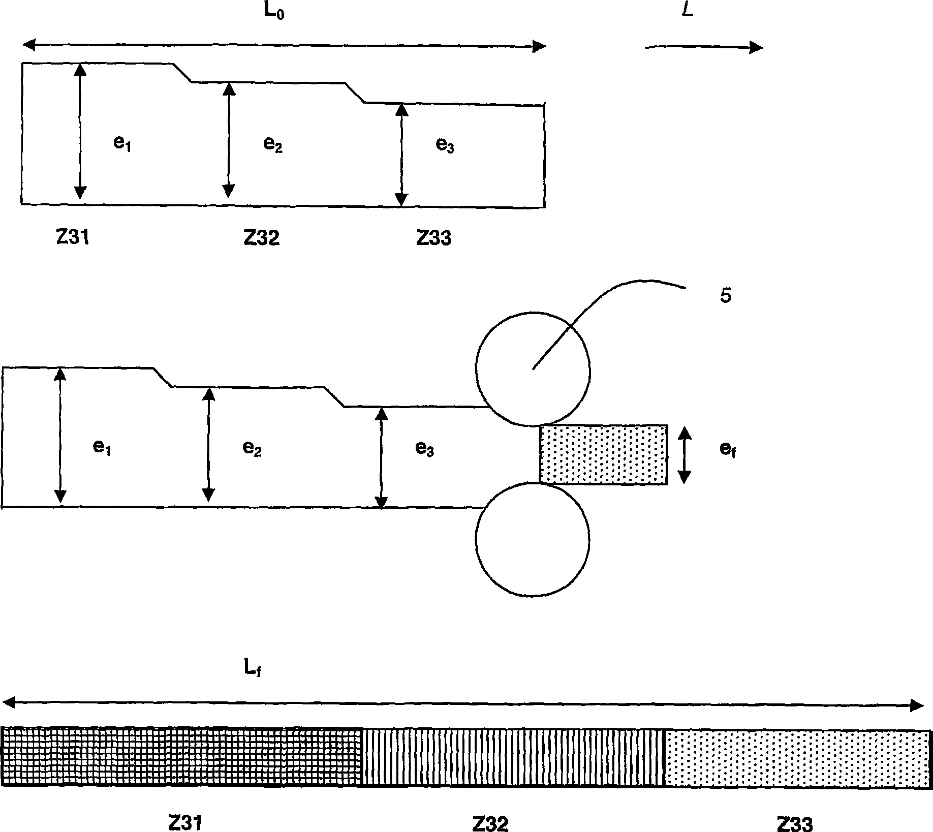
[0093] After hot rolling, the plates are image 3 Machining is carried out as shown to obtain three zones Z31, Z32 and Z33 with a length equal to 10 meters and a thickness as follows:

[0094] Zone Z31: 28.1mm

[0095] Zone Z32: 26.3mm

[0096] Zone Z33: 25.5mm

[0097] The plate was then solution treated and quenched at 500°C.

[0098] The sheet is th...

Embodiment 2

[0108] In this example, a plate made of alloy AA2024A with a thickness of 15 mm and spatially variable properties was obtained.

[0109] By hot-rolling the rolled slab, a plate with a length of 30 meters, a width of 2.5 meters, and a thickness of 16.8 mm was manufactured.

[0110] The composition of the alloy used is shown in Table 4 below:

[0111] Table 4: Composition of alloy AA2024A rolled slabs (mass%)

[0112] Si Fe Cu mn Mg Ti 0,04 0,07 3,96 0,38 1,29 0,013

[0113] The rolled slab is homogenized and then hot rolled.

[0114] After hot rolling, the plates are image 3 Machining is carried out as shown to obtain three zones Z31, Z32 and Z33 with a length equal to 10 meters and a thickness as follows:

[0115] Zone Z31: 16.7mm

[0116] Zone Z32: 15.9mm

[0117] Zone Z33: 15.3mm

[0118] The plate was then solution treated and quenched at 500°C.

[0119] The sheet is then cold rolled to obtain a substantially constant thickness of 1...

Embodiment 3

[0129] In this example, a profile made of alloy AA2027 with a section of 170×45 mm and with spatially variable properties was obtained.

[0130] A profile with a length of 15 meters and a section of 170×45 mm was manufactured by hot extrusion of the drawn billet.

[0131] The composition of the alloy used is shown in Table 7 below:

[0132] Table 7: Composition of alloy AA2027 rolled slabs (mass%)

[0133] Si Fe Cu mn Mg Zn Ti Zr 0,05 0,11 4,2 0,6 1,3 0,06 0,02 0,11

[0134] The drawn billet was homogenized at 490°C and then hot extruded.

[0135] After drawing, the profile is solution treated and quenched at 500°C.

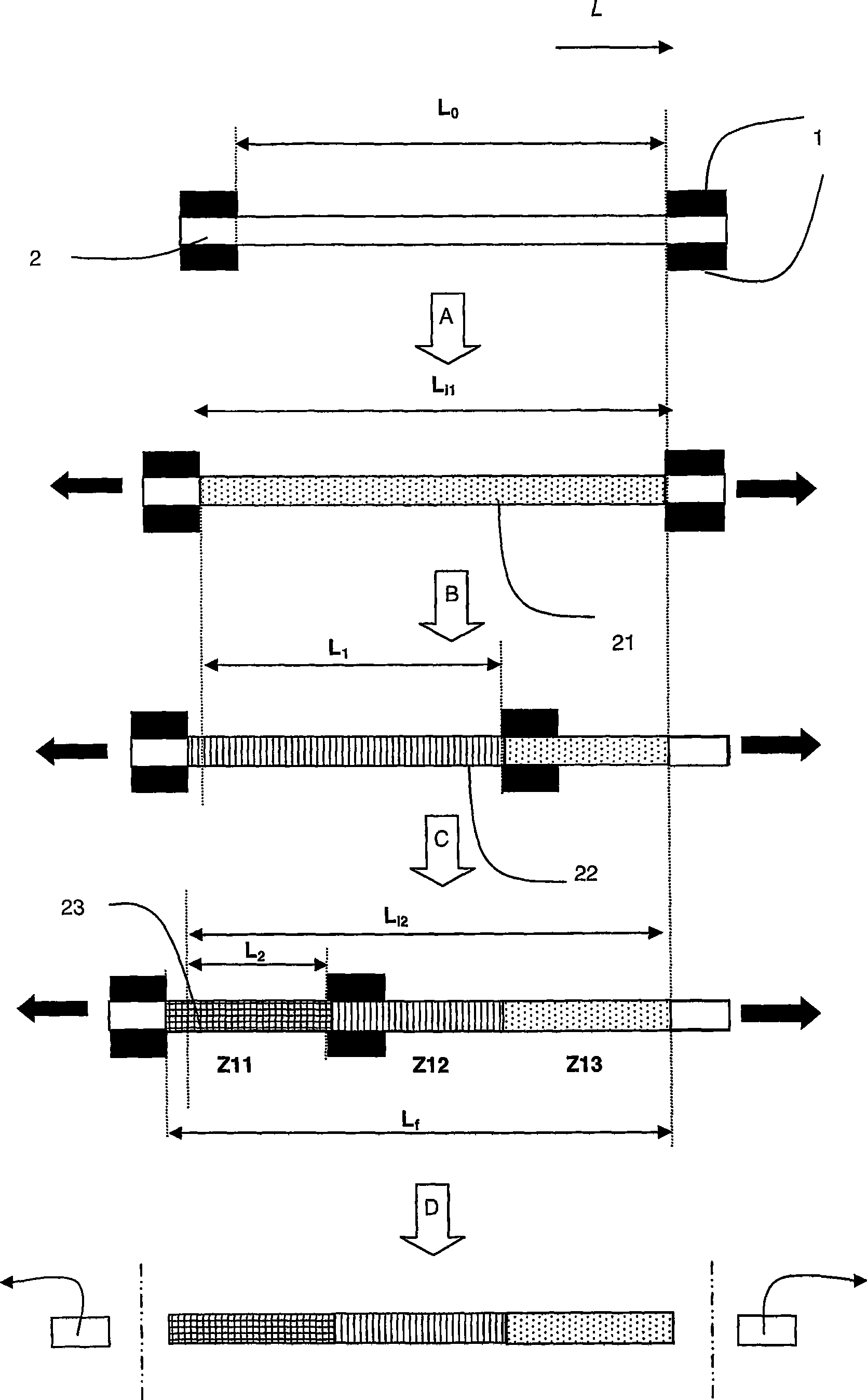
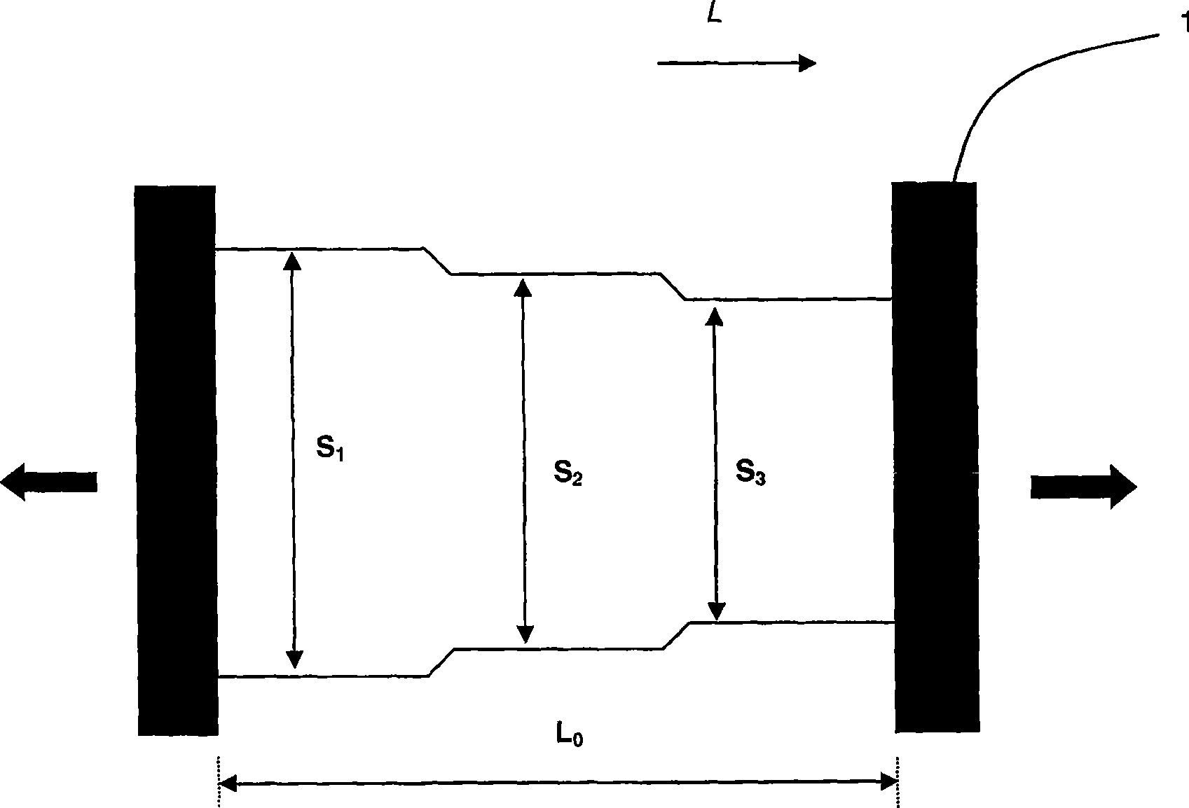
[0136] A first step of controlled stretching was then performed to permanently elongate it by 2.8%. Then make one claw of the stretching table such as figure 1 Move as shown so that one end of the profile protrudes beyond the claw. A second stretching step was then carried out on the two thirds of the profile between th...


PUM


Abstract

The invention relates to a method for producing a processing product made by aluminum alloy or an integral multifunctional structural element made by the aluminum alloy. The method comprises the step of thermal process, being characterized in that the method also comprises a step of processing cold plasticity deformation after the thermal process. The structural element imposed by the difference between the two regions at least at least 2% of the average generalized plastic deformation, at least 3% of the difference between preferred. Preparation of this invention can be used for aeronautical engineering in particular, the structure of components, components in the space above with the use of variable nature, and at the same time with the existing components have the same shape characteristics. The present invention method and has a controlled economy, it did not temper the major components to enable the use of the nature of change.

Description

technical field [0001] The invention relates to fabricated products and structural elements made of aluminum alloys, which are used in particular in aeronautical engineering. The processed product may be a rolled product (eg sheet, medium thickness plate, thick plate), drawn product (eg bar, profile, pipe or wire) and a forged product. Background technique [0002] Integral metallic structural elements with spatially variable properties show great benefit in current aerospace industry conditions. In fact, this structural element is acted upon by a set of opposing stresses, which requires a particular choice of materials and deformation conditions, which may lead to less than satisfactory compromises. Furthermore, the overall machining steps that replace time-consuming and expensive mechanical assembly steps with more economical monolithic components are limited by the ability to achieve optimal performance in each geometrical area within the monolithic component. Therefore...

Claims


Application Information

Patent Timeline
Patent Type & Authority Applications(China)
IPC IPC(8): C22F1/04C22F1/057C22C21/16
CPCC22F1/057C22F1/04C22C21/18C22C21/14C22C21/12B21B2205/02C22C21/16
Inventor P·勒奎尤F·海梅斯A·丹尼路
Owner CONSTELLIUM ISSOIRE
Learn More