
Modular closed low-speed direct-current wind tunnel

A closed-end, modular technology, applied in the field of aeronautical engineering dynamics, can solve the problems of limited test capacity and test performance, insufficient strength of wooden structures, inconvenient movement, etc., to achieve high practicability, adaptability, and light weight , The effect of convenient and quick operation

Active Publication Date: 2020-07-10
西安老鹰航空科技有限公司
View PDF3 Cites 2 Cited by
  • Summary
  • Abstract
  • Description
  • Claims
  • Application Information

AI Technical Summary

Problems solved by technology

[0003] Existing wind tunnels are generally divided into two categories. The first category is large-scale wind tunnels. The overall structure adopts a relatively thick steel structure, which is heavy in weight. In order to ensure safe use, it is often integrated with the building during installation, which cannot be convenient. Mobile, its power unit is also single and cannot be replaced to improve test performance; the second type is miniaturized wind tunnels, which generally use wooden structures. Although they are light in weight, the test section is very small, which greatly limits their test capabilities. and test performance. In addition, due to the insufficient strength of the wooden structure, the wooden structure is prone to vibration and excessive noise during the test, which limits the increase of the test wind speed.

Method used


Image

  • Modular closed low-speed direct-current wind tunnel
  • Modular closed low-speed direct-current wind tunnel
  • Modular closed low-speed direct-current wind tunnel

Examples


Embodiment 1

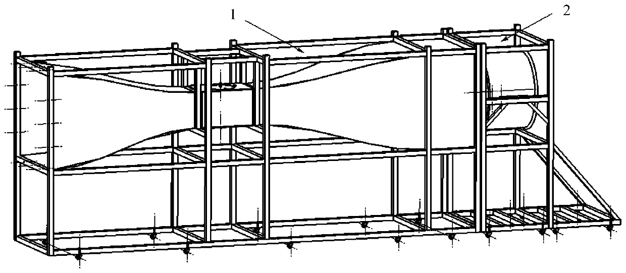
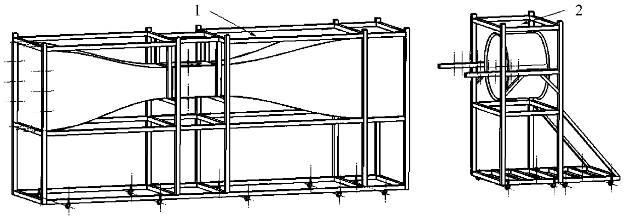
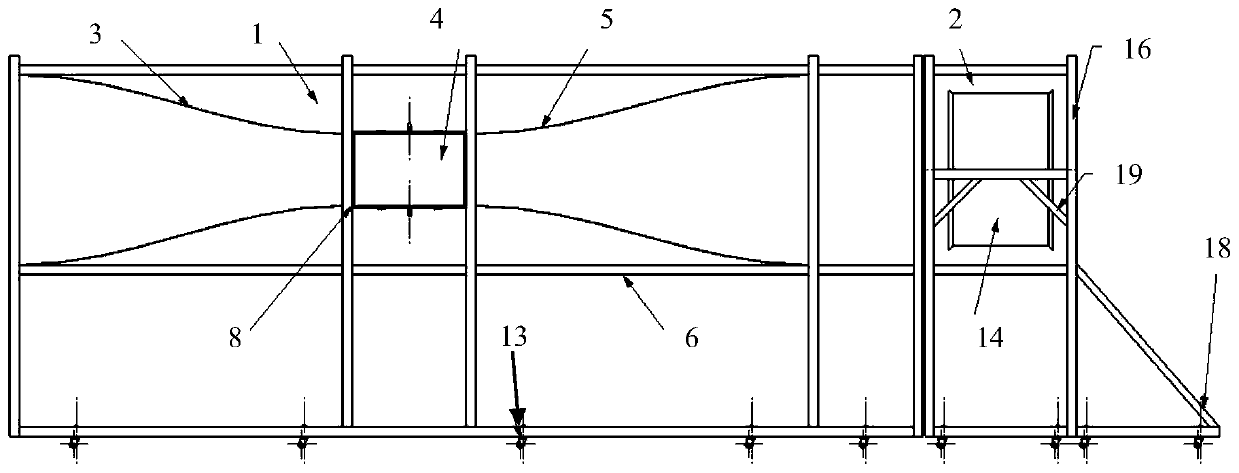
[0023] Embodiment 1, a modular closed low-speed direct current wind tunnel, such as figure 1 and figure 2 As shown, it includes cave structure 1 and power system 2. The cave body structure 1 comprises a cave body support 6, and the cave body support 6 is successively provided with an air intake section 3, a test section 4 and an expansion section 5 (see image 3 ), the inlet section 3, the test section 4 and the expansion section 5 are streamlined. The power system 2 includes a blower fan 14, a moving slide rail 15 and a power support 16; the cave structure 1 and the power system 2 are docked through the moving slide rail 15 (see Figure 6 ); the two sides of the outer wall of the fan 14 are respectively welded with fan connecting lugs 17, and the fan connecting lugs 17 are bolted to the moving slide rail 15; the upper surface and the lower surface of the moving slide rail 15 are respectively provided with ten equally spaced oval The through hole is welded between the movi...


PUM


Abstract

The invention relates to the field of aeronautical engineering dynamics, and discloses a modular closed low-speed direct-current wind tunnel. The wind tunnel comprises a tunnel body structure and a power system, and is characterized in that the tunnel body structure comprises a tunnel body bracket, and the tunnel body bracket is sequentially provided with an air inlet section, a test section and an expansion section; the power system comprises a draught fan, a movable sliding rail and a power support; the tunnel body structure is in butt joint with the power system through the movable slidingrail; fan connecting lugs are welded to the two sides of the outer wall of the fan correspondingly and connected with the movable sliding rail through bolts; a plurality of through holes are formed inthe upper surface and the lower surface of the movable sliding rail respectively, and the movable sliding rail is connected with the power support. The whole structure has the characteristic of modularization, the performance is reliable and stable, the use and operation are very convenient and fast, the practicability and adaptability are high, the hole body structure and the power system both adopt independent movable brackets, and the weight is low; and the tunnel wall adopts a streamline design meeting aerodynamic requirements, so that the whole operation is more energy-saving and environment-friendly.

Description

technical field [0001] The invention relates to the field of aeronautical engineering dynamics, in particular to a modular closed low-speed DC wind tunnel. Background technique [0002] The wind tunnel is a special aerodynamic test equipment in the field of aeronautical engineering. It is used to conduct aerodynamic tests of aircraft, and can be extended to aerodynamic tests of vehicles, high-speed trains, buildings, propellers and other products. [0003] Existing wind tunnels are generally divided into two categories. The first category is large-scale wind tunnels. The overall structure adopts a relatively thick steel structure, which is heavy in weight. In order to ensure safe use, it is often integrated with the building during installation, which cannot be convenient. Mobile, its power unit is also single and cannot be replaced to improve test performance; the second type is miniaturized wind tunnels, which generally use wooden structures. Although they are light in wei...

Claims


Application Information

Patent Timeline
IPC IPC(8): G01M9/02G01M9/04
CPCG01M9/02G01M9/04
Inventor 谢辉
Owner 西安老鹰航空科技有限公司
Learn More