
Electroplating device and method

An electrolytic coating and coating technology, applied in the field of electrolytic coating devices and methods, can solve problems such as being unable to be used for coating, long devices, etc., and achieve the effect of small intervals

Inactive Publication Date: 2009-05-06
BASF AG
View PDF2 Cites 9 Cited by
  • Summary
  • Abstract
  • Description
  • Claims
  • Application Information

AI Technical Summary

Problems solved by technology

[0006] A disadvantage of the methods known from the prior art is that they cannot be used to coat structures that are especially short as viewed in the transport direction of the substrate
Another disadvantage is that in order to produce a sufficiently long contact time, many rollers connected in series are required, requiring a very long setup

Method used


Image

  • Electroplating device and method
  • Electroplating device and method
  • Electroplating device and method

Examples


Embodiment Construction

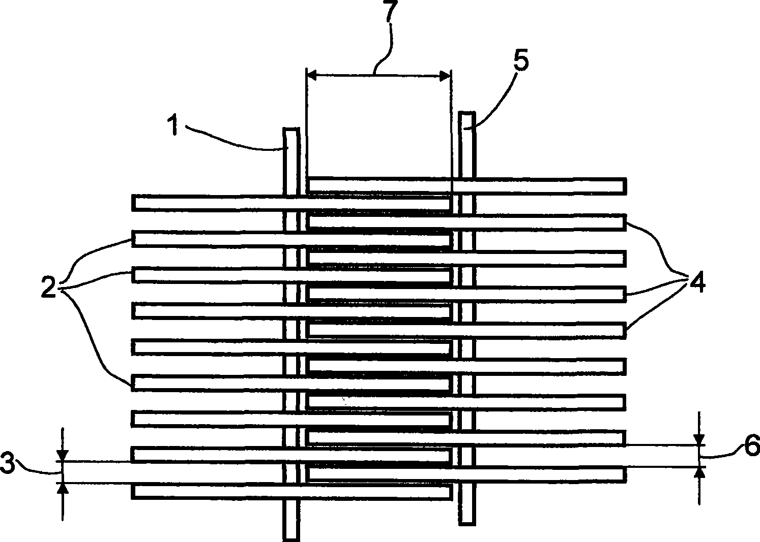
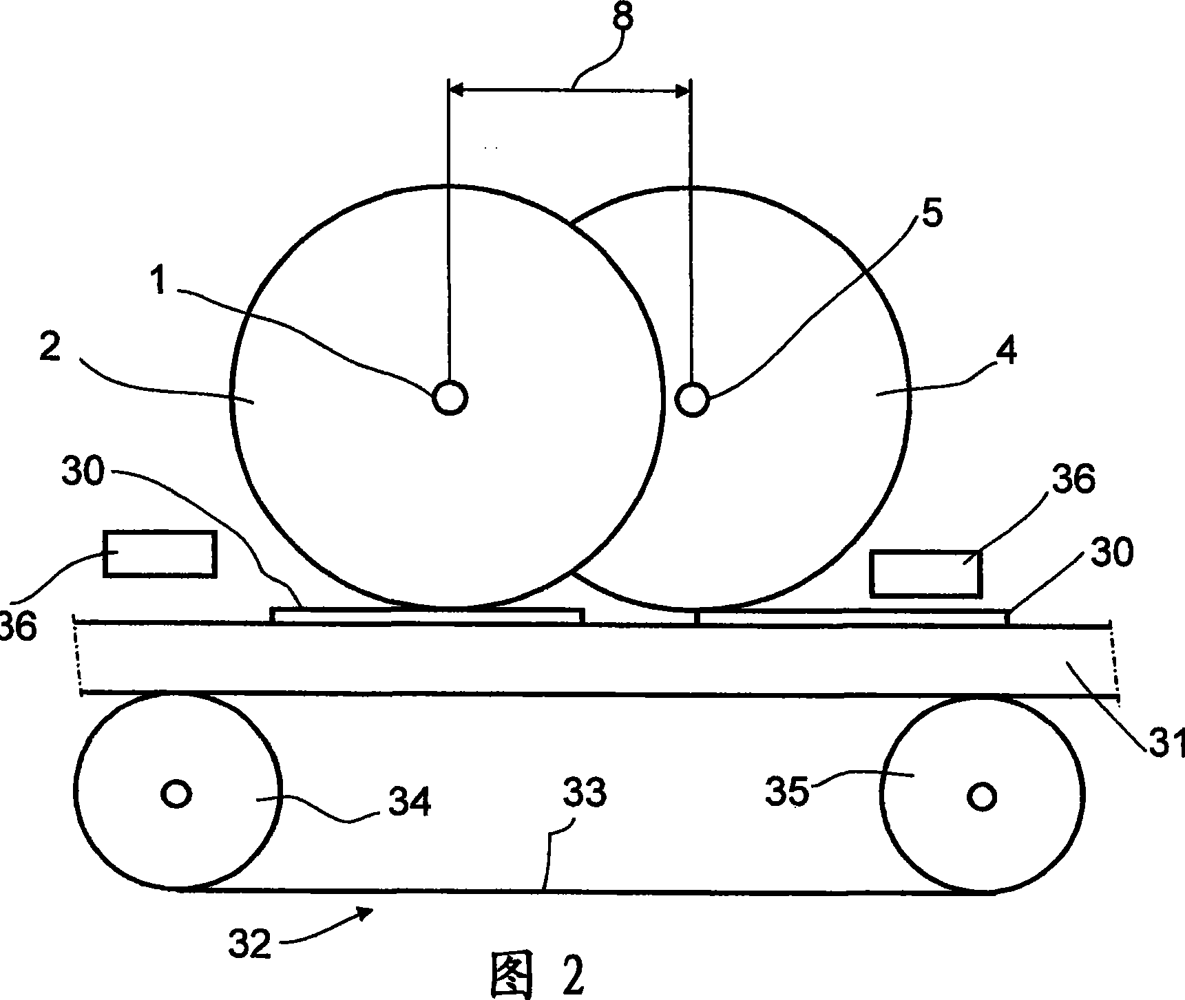
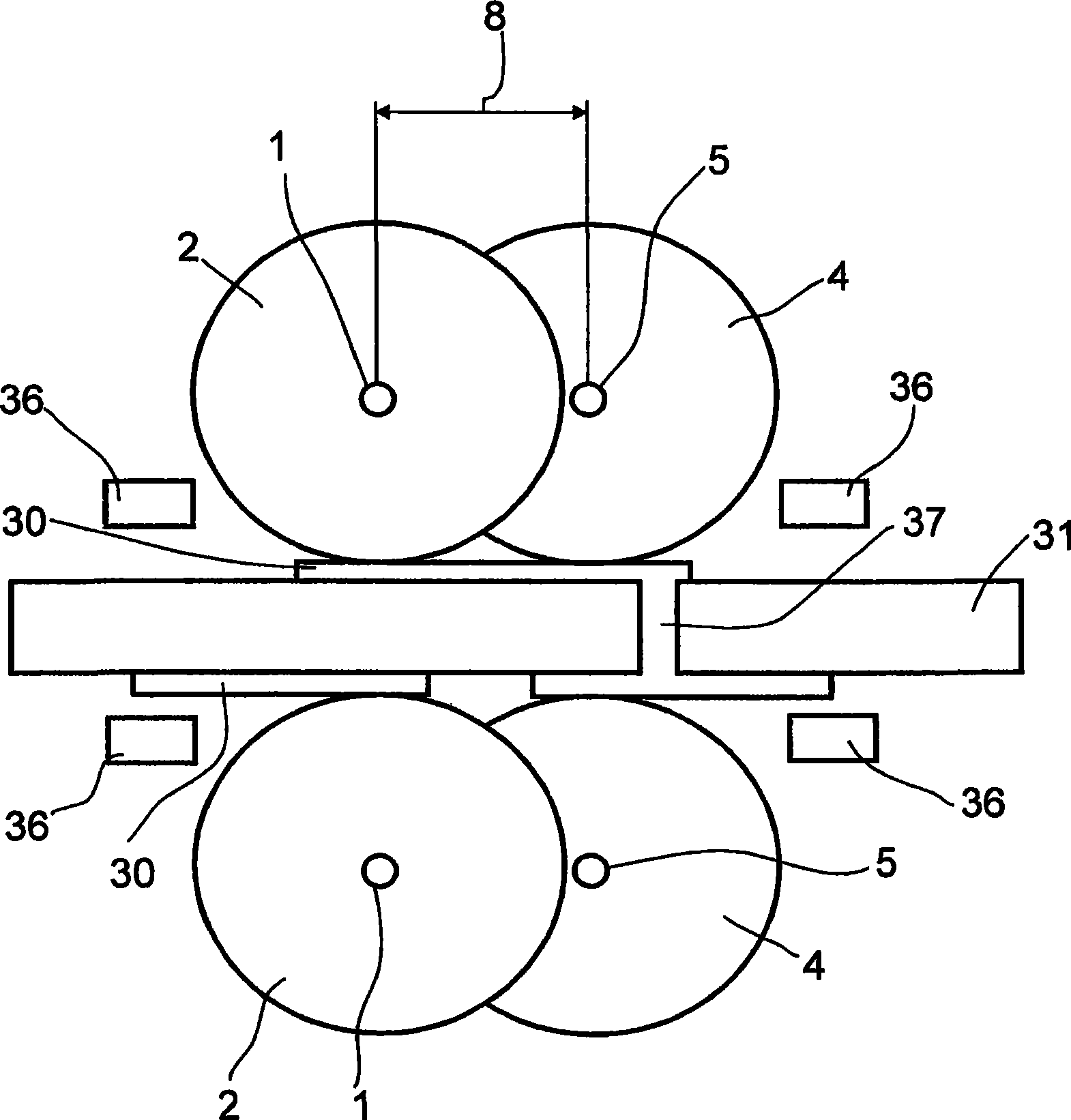
[0060] figure 1 A top view of a device designed according to the invention is shown. A certain number of first disks 2 are arranged on the first shaft 1 . The disks 2 are mounted on the shaft 1 at intervals 3, respectively. The space 3 is chosen such that the disc 4 fastened on the second shaft 5 can engage therein. The spacing 6 of the second disks 4 is chosen such that the first disk 2 can engage between two second disks 4 respectively.

[0061] exist figure 1 In the illustrated embodiment, the first disc 2 mounted on the first shaft 1 and the second disc 4 mounted on the second shaft 5 each have the same width (thickness). However, discs with different widths can also be provided. In this case, disks of equal width may be arranged on one shaft, respectively, and disks of a different width from those on the first shaft are arranged on a second shaft, or disks of different widths may be mounted on one shaft. When discs of different widths are mounted on one shaft, the s...


PUM


Abstract

The invention relates to a device for electroplating at least one electrically conductive substrate or a structured or electrically conductive surface covering the whole area of a non-conductive substrate. Said device comprises at least one bath, an anode and a cathode. The bath contains an electrolyte solution, which comprises at least one metal salt and from which metal ions are deposited on electrically conductive surfaces of the substrate to form a metal layer, as the cathode is brought into contact with the surface of the substrate to be coated and said substrate is conveyed through the bath. The cathode comprises at least two discs (2, 4, 10) that are rotatably mounted on a respective shaft (1, 5, 14), said discs (2, 4, 10) intermeshing. The invention also relates to a method for electroplating at least one substrate, said method being carried out in a device according to the invention. The invention further relates to the use of said device for electroplating electrically conductive structures situated on an electrically non-conductive support.

Description

technical field [0001] The invention relates to a method for the electrolytic coating (electroplating) of at least one conductive substrate or of a structured (structured) or completely surfaced (full-surface) conductive surface on a non-conductive substrate Apparatus comprising at least one electrolytic cell, an anode and a cathode, the electrolytic cell containing at least one electrolyte solution containing a metal salt from which metal ions are deposited on a conductive surface of the substrate to form metal layer. [0002] The invention also relates to a method for the electrolytic coating of at least one substrate implemented in a device designed according to the invention. Background technique [0003] Electrolytic coating methods are used, for example, to coat structured or fully surfaced conductive surfaces on conductive or non-conductive substrates. For example, these methods enable the production of conductor tracks on printed circuit boards, RFID antennas, flat...

Claims


Application Information

Patent Timeline
Patent Type & Authority Applications(China)
IPC IPC(8): C25D7/06C25D17/00C25D7/00
CPCC25D17/28C25D7/0657C25D17/005C25D17/06C25D17/00C25D7/00C25D17/12C25D17/02C25D17/10
Inventor R·洛赫特曼J·卡祖恩N·施奈德J·普菲斯特G·波尔N·瓦格纳
Owner BASF AG
Learn More