Centrifugal casting apparatus and metal mould replacing method

A metal mold and centrifugal casting technology, which is applied in the field of centrifugal casting devices, can solve the problems of low operation rate of centrifugal casting devices, long time and need for a long time, and achieves the effect of good operation efficiency and improved operation rate.

Active Publication Date: 2012-05-30
KUBOTA LTD
View PDF0 Cites 0 Cited by
  • Summary
  • Abstract
  • Description
  • Claims
  • Application Information

AI Technical Summary

Problems solved by technology

When replacing metal molds 51 of different sizes, after a part of the sealing portion 54 must be removed together with the metal mold 51 and the sleeve 52, these metal molds 51 and the sleeve 52 are taken out from the outer frame 56 along the axial direction, and the The centrifugal casting device has to be stopped during the operation, and it takes a long time to remove a part of the sealing part 54.
In addition, since the driving force transmission member 58 is composed of a belt that transmits the rotational driving force of the motor 57 to the sleeve 52, and the driving force transmission member 58 is arranged to penetrate the outer frame 56, the work of removing the driving force transmission member 58 may be It takes a long time to further adjust the relative height of the position of the metal mold 51 to the position of injecting the molten metal.
That is, in such Figure 14 In the rotary water tank type centrifugal casting device shown, when the metal mold 51 is replaced, the centrifugal casting device must be stopped for a long time, and there is a disadvantage that the operating rate of the centrifugal casting device is lowered.

Method used


Image

  • Centrifugal casting apparatus and metal mould replacing method
  • Centrifugal casting apparatus and metal mould replacing method
  • Centrifugal casting apparatus and metal mould replacing method

Examples


Embodiment Construction

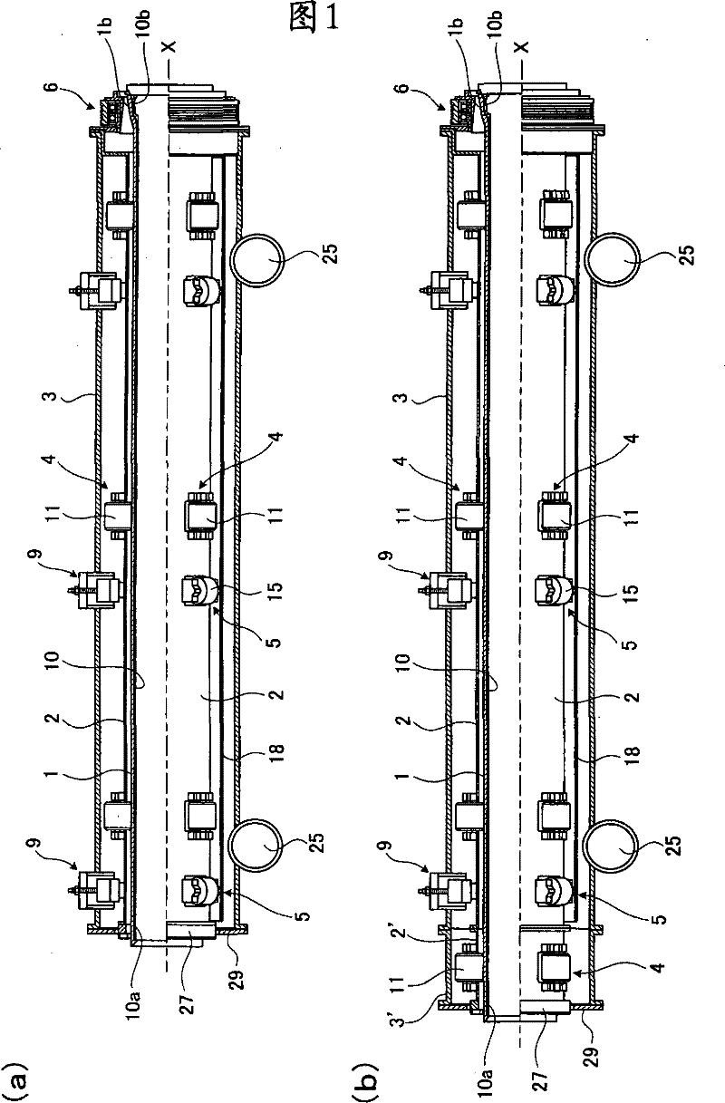
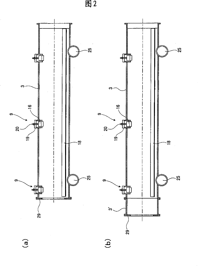
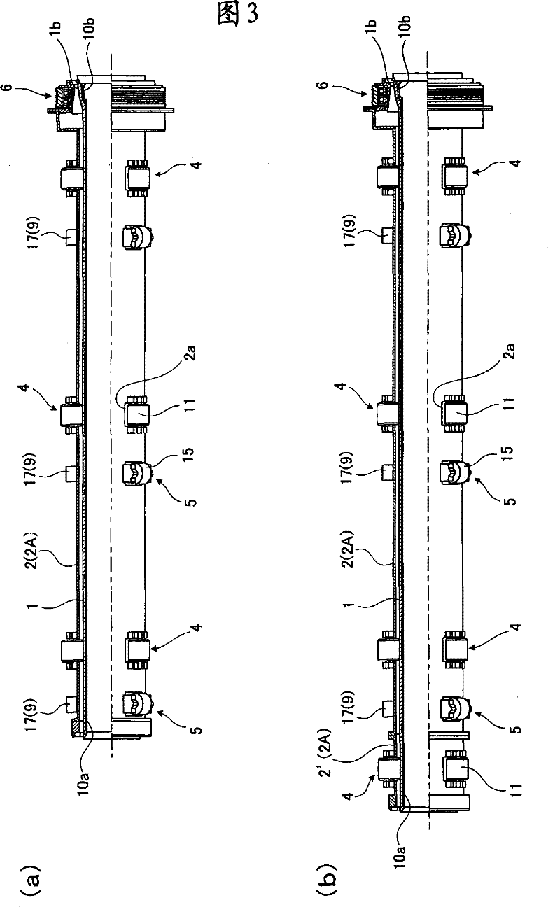
[0049] Hereinafter, a centrifugal casting device and a die replacement method according to an embodiment of the present invention will be described in detail with reference to the drawings. figure 1 (a) and figure 1 (b) are partial cut-away front views of the whole centrifugal casting device related to the embodiment of the present invention; figure 2 (a) and figure 2 (b) are the front sectional views of the outer frame of the centrifugal casting device; image 3 (a), image 3 (b), Figure 4 (a) and Figure 4 (b) are partial cutaway front views of the inner frame of the centrifugal casting device, respectively. in addition, figure 1 (a), figure 2 (a), image 3 (a), Figure 4 (a) represents a centrifugal casting device for casting a short metal mold for casting a metal pipe with a short length along the axial direction; figure 1 (b), figure 2 (b), image 3 (b), Figure 4 (b) shows a centrifugal casting apparatus for a long metal mold for casting a metal pip...


PUM


Abstract

The invention discloses a centrifugal casting device, through which a cylinder-shaped metal die (1) rotates around a shaft center (X) and molten metal flows into the inner side of the metal die (1), a metal pipe (10) is cast by utilizing a centrifugal force, the metal die (1) is cooled by cooling water from the outer side during casting, wherein, the centrifugal casting device is provided with anouter frame (3) matched at the feeding part of the molten metal, an inner frame (2) which can be freely moved and replaced outside the outer frame (3) under the condition that the metal die (1) keepsfreely rotating around the shaft center, a cooling water leading-in mechanism arranged between the inner frame outside the outer frame and the metal die for leading-in cooling water and a rotary driving force conveying part (6), which conveys the rotary driving force to the metal die (1) maintained in the inner frame so as to rotate. Therefore, at the rotating stage of the centrifugal casting device, the centrifugal casting device can carry out the following operation in advance or carry out the para-position operation such as posture maintaining of the metal die (1) relative to the inner frame (2) for centrifugal casting next time.

Description

technical field [0001] The invention relates to a centrifugal casting device for casting a metal pipe by centrifugal force and a method for replacing a metal mold. Background technique [0002] A centrifugal casting method is known in which molten metal is poured into the inside of the metal mold while rotating a cylindrical metal mold around its axis in a state in which the axis of the metal mold is horizontal, thereby casting by centrifugal force. A pipe made of cast iron or other metal with a socket at one end and a socket at the other end. In this centrifugal casting method, since casting is performed while applying a centrifugal force while pressurizing, there is an advantage that a dense metal tube with few impurities can be obtained. [0003] As a centrifugal casting device used in such a centrifugal casting method, there is known a water-cooled centrifugal casting device that performs centrifugal casting while cooling a metal mold with cooling water from the outside...

Claims


Application Information

Patent Timeline
Patent Type & Authority Patents(China)
IPC IPC(8): B22D13/02
Inventor 水田清继关口靖史田中进一郎山户一弘
Owner KUBOTA LTD
Why Eureka
Try Eureka