
Multicenter burner gas distributer for short-process reduction zinc powder fabrication

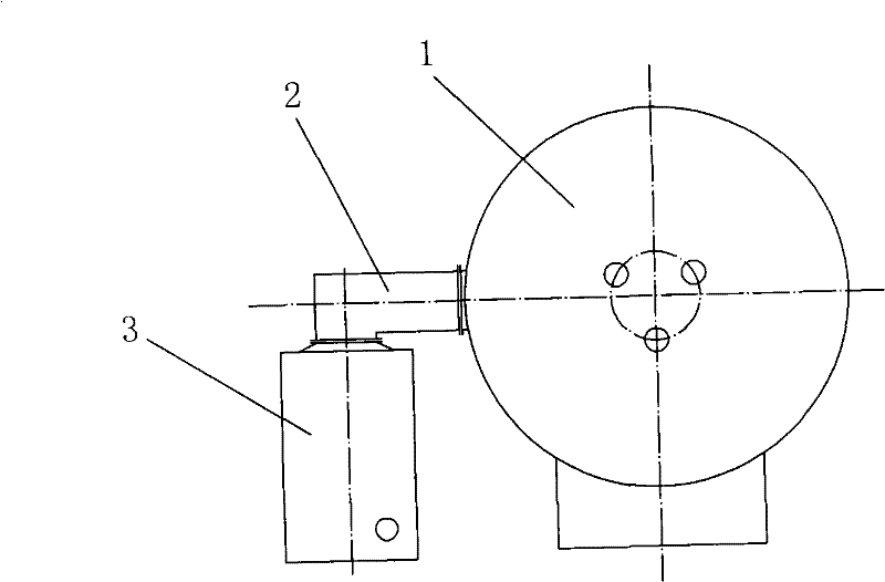
A multi-channel, short-flow technology, applied in separation methods, dispersed particle separation, chemical instruments and methods, etc., can solve problems such as safety accidents, furnace pressure rise, equipment safety accidents, etc., to prevent furnace gas leakage and reduce The equipment occupies an area and the effect of eliminating the blockage of the furnace throat

Active Publication Date: 2011-07-27
ZHUZHOU FLASHLIGHT IND FURNACE
View PDF0 Cites 0 Cited by
  • Summary
  • Abstract
  • Description
  • Claims
  • Application Information

AI Technical Summary

Problems solved by technology

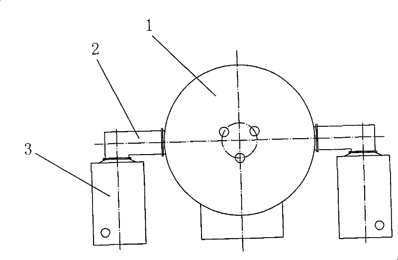
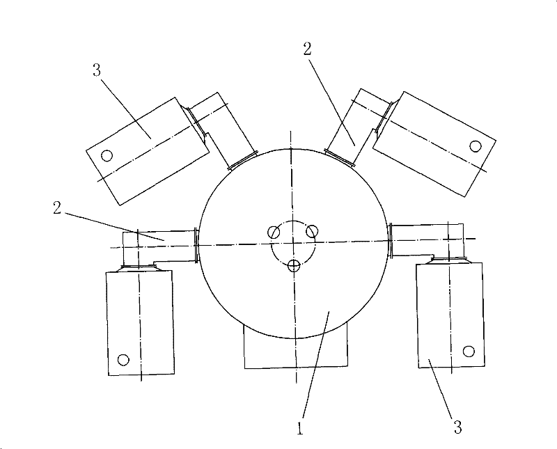
In order to solve the contradiction between the production capacity of the two main equipments, the existing method is to configure two or more sets of furnace throats and condensers in one closed submerged heat electric furnace (for equipment configuration, see figure 2 and image 3 ), although the problem of capacity matching of the two main equipments has been solved, the following insurmountable defects have been produced: the furnace gas generated by the closed submerged heat electric furnace is unevenly distributed on each condenser, resulting in that the capacity of the condenser cannot be fully utilized and The production process is unstable
[0007] ①. The agglomeration speed and agglomeration size of the furnace gas channels of the two furnace throats cannot be the same, so the airflows flowing to the two condensers at the same time are different in size, one of which is under load and the other is overloaded. If the balance reaches a certain level, the output will decrease sharply, and even lead to safety accidents.
[0008] ②. In the process of cleaning the furnace throat, it is impossible to ensure that it is cleaned at the same time, and it is also impossible to ensure that the furnace gas passages of the cleaned furnace throat are of the same size, so it is also impossible to ensure that the furnace gas flows evenly to the two condensers
[0010] ① There is no ash hopper and ash discharge device in the furnace throat. When cleaning the ash and agglomerates inside, the ash and agglomerates can only be pushed into the closed submerged heat electric furnace, which is extremely inconvenient to operate
However, when cleaning the furnace throat, ash and agglomerates containing some metal zinc suddenly enter the molten pool, resulting in a large amount of zinc vapor and a sharp increase in furnace pressure. Occurrence of security incidents

Method used


Image

  • Multicenter burner gas distributer for short-process reduction zinc powder fabrication
  • Multicenter burner gas distributer for short-process reduction zinc powder fabrication
  • Multicenter burner gas distributer for short-process reduction zinc powder fabrication

Examples


Embodiment 1

[0039] Such as Figure 5 with Image 6 As shown, a multi-channel furnace gas distributor for the production of short-process reduced zinc powder, the upper part is a multi-channel furnace gas distribution chamber 7, the middle part is an ash hopper 8, the lower part is an ash discharge device 9, and the multi-channel furnace gas distribution chamber 7. The ash hopper 8 and the ash discharge device 9 are connected and combined to form a whole.

[0040] The multi-channel furnace gas distribution chamber 7 is a polyhedral cavity made of metal material with multiple openings and lined with refractory materials.

[0041] Among the openings, one opening on the side is connected to the furnace gas outlet of the closed submerged heat furnace 1; the number of remaining openings on the side is equal to the number of condensers 3, and each opening is connected to a condenser 3.

[0042] The ash collecting bucket 8 is a polyhedron cavity with perforations on both sides of the upper and ...

Embodiment 2

[0051] Such as Figure 7 with Figure 8 As shown, a multi-channel furnace gas distributor for the production of short-process reduced zinc powder, the upper part is a multi-channel furnace gas distribution chamber 7, the middle part is an ash hopper 8, the lower part is an ash discharge device 9, and the multi-channel furnace gas distribution chamber 7. The ash hopper 8 and the ash discharge device 9 are connected and combined to form a whole.

[0052] The above-mentioned multi-channel furnace gas distribution chamber 7 is a polyhedron cavity with multi-face openings and a water jacket with an interlayer made of metal material.

[0053] Among the openings, one opening on the side is connected to the furnace gas outlet of the closed submerged heat furnace 1; the number of remaining openings on the side is equal to the number of condensers 3, and each opening is connected to a condenser 3.

[0054] The ash collecting bucket 8 is a polyhedron cavity with perforations on both si...


PUM


Abstract

The invention discloses a multichannel furnace gas distributor for manufacturing short stage reducing zinc dust. The furnace gas distributor mainly comprises three parts: an upper part is the multichannel furnace gas distributor; a center part is a dust formation hopper; a lower part is an ash exhauster; and the three parts are connected to form a whole. The distributor can ensure that a large scale closed-loop ore-smelting electric furnace can be effectively configured with a plurality of condensers at the same time, which meets the requirement of production line upsizing of the short stage reducing zinc dust and eliminates the restriction of a single channel furnace throat on device upsizing. After optimization design on the multichannel furnace gas distributor, the multichannel furnacegas distributor ensures that furnace gas uniformly flows into a plurality of condensers. The invention eliminates the influence of the flow section variation of the single channel furnace throat on quantity of air flow which enters each condenser, realizes that the each condenser produces in uniform load, and ensures that each condenser gives play to capability. The distributor can play a role ineliminating furnace throat blockage, guaranteeing sealing power discharging, and preventing furnace gas escaping, thus enabling the development requirement of the short stage reducing zinc dust.

Description

technical field [0001] The invention relates to non-ferrous metal smelting equipment, in particular, the invention is a multi-channel furnace gas distributor for the production of short-flow reduced zinc powder. Background technique [0002] At present, the short-process reduced zinc powder is mainly used as a displacer in the non-ferrous metal smelting process. Because of its fine particle size, good activity, low cost and many other advantages, it has basically replaced blown zinc powder and distilled zinc powder in this industry. The main equipment of the process includes: a closed submerged heat electric furnace 1, a furnace throat 2, and a condenser 3. Its technological process comprises following three steps (see equipment configuration figure 1 ): [0003] a. Put zinc-containing materials, reducing agent and flux into the closed submerged thermal electric furnace 1. Under the appropriate temperature and atmosphere in the furnace, the oxidized zinc in the furnace cha...

Claims


Application Information

Patent Timeline
Patent Type & Authority Patents(China)
IPC IPC(8): B01D51/00F27B3/22F27B3/08
Inventor 熊家政鲁志昂龙会国
Owner ZHUZHOU FLASHLIGHT IND FURNACE
Learn More