Test piece for implementing biaxial tension-compression coupling stress state through uniaxial tension
A technology of coupled stress and unidirectional stretching, applied in the direction of measuring devices, instruments, scientific instruments, etc., can solve the problems of increasing the complexity of experimental operations, large errors in test results, and complicated test equipment, so as to avoid two-way synchronous and coordinated loading, Easy to use effects
- Summary
- Abstract
- Description
- Claims
- Application Information
AI Technical Summary
Problems solved by technology
Method used
Image

Examples
Embodiment Construction
[0016] The present invention provides a test piece that achieves bidirectional tension-compression coupled stress state through unidirectional tension. The present invention will be further described below in conjunction with the description of the drawings and specific implementation methods.
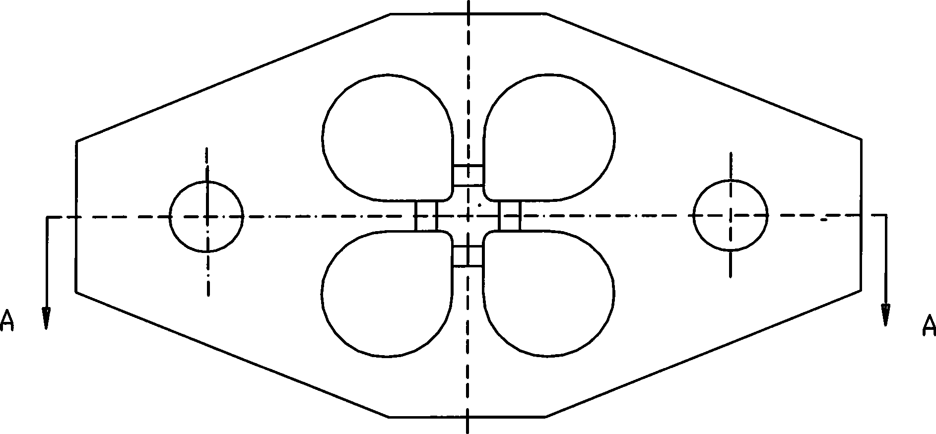
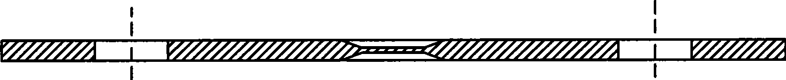
[0017] Fig. 1 (a) is a top view of the test piece of the present invention; Fig. 1 (b) is a sectional view of the A-A surface of the test piece of the present invention. The material of the test piece is low-carbon steel, and the outer contour is octagonal, wherein the length of the major axis L1=150mm, the length of the minor axis W1=80mm, the length of the side parallel to the major axis L2=30mm, and the length of the side parallel to the minor axis Side length W2 = 30mm; two circular holes are symmetrically arranged at both ends of a longer central axis of the test piece, used to load the fixture of the tensile testing machine, and the distance between the center of the circular hole...
PUM
| Property | Measurement | Unit |
|---|---|---|
| Thickness | aaaaa | aaaaa |
| Major axis length | aaaaa | aaaaa |
| Minor axis length | aaaaa | aaaaa |
Abstract
Description
Claims
Application Information
 - Generate Ideas
- Intellectual Property
- Life Sciences
- Materials
- Tech Scout
- Unparalleled Data Quality
- Higher Quality Content
- 60% Fewer Hallucinations
Browse by: Latest US Patents, China's latest patents, Technical Efficacy Thesaurus, Application Domain, Technology Topic, Popular Technical Reports.
© 2025 PatSnap. All rights reserved.Legal|Privacy policy|Modern Slavery Act Transparency Statement|Sitemap|About US| Contact US: help@patsnap.com