Input device with physiological signal sensing module
An input device and signal technology, applied in the input/output process of data processing, sensors, electrical digital data processing, etc., can solve problems such as low reliability, user's hand fatigue and discomfort, poor sensing effect, etc., to achieve Effects of overcoming differences in personal habits, ensuring reliability, and increasing the sensing area
- Summary
- Abstract
- Description
- Claims
- Application Information
AI Technical Summary
Problems solved by technology
Method used
Image
Examples
no. 1 example
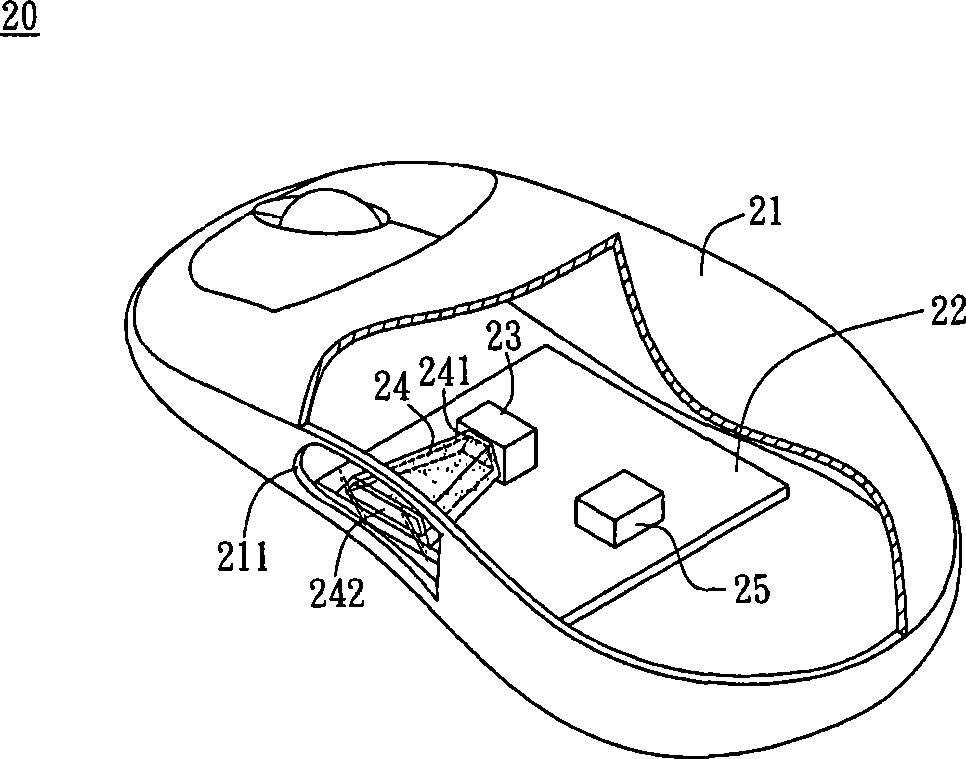
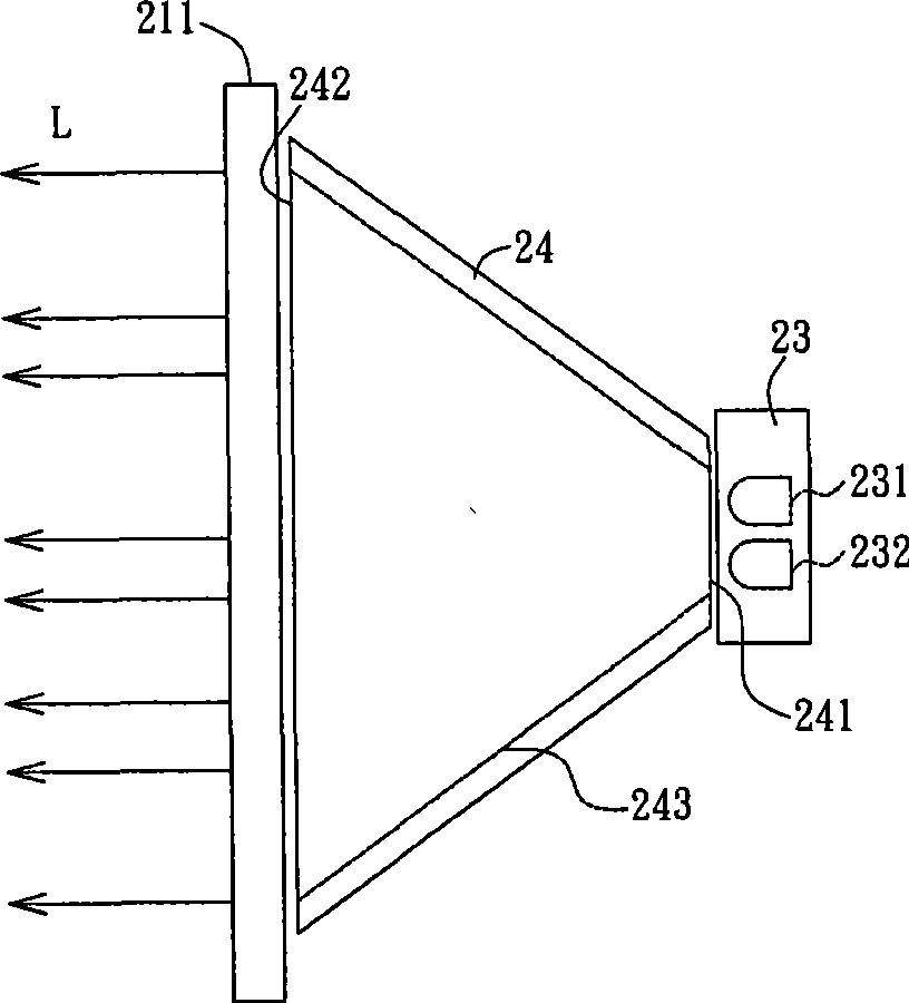
[0023] Please refer to Figure 2A and Figure 2B As shown, the input device 20 with a physiological signal sensing module in this embodiment includes a housing 21 , a circuit board 22 , a sensing module 23 and a light guide element 24 . In this embodiment, the housing 21 has a light-transmitting grip portion 211, the sensing module 23 is disposed on the circuit board 22 and electrically connected to the circuit board 22, and the circuit board 22 is disposed in the housing 21. In addition, the light guide element 24 is disposed between the sensing module 23 and the transparent handle 211 . Herein, the corresponding arrangement of the sensing module 23 and the light-transmitting grip portion 211 is used as an example for illustration, but it is not intended to limit the present invention.
[0024] The sensing module 23 of this embodiment has at least one light emitting element 231 and one sensing element 232 . Wherein, the light emitting element 231 may be a light emitting di...
no. 2 example
[0032] Please refer to Figure 5A and Figure 5B As shown, another preferred embodiment of the input device with a physiological signal sensing module of the present invention is illustrated, wherein Figure 5B yes Figure 5A A schematic diagram of the path of light L emitted by the light emitting element 231 in FIG. The input device 20a of this embodiment includes a casing 21, a circuit board 22, a sensing module 23 and a light guide element 24a. The light guide element 24 a is disposed between the sensing module 23 and the light-transmitting grip portion 211 . The position of the sensing module 23 can be adjusted according to actual needs or according to the layout of the circuit board 22 . Therefore, it is taken as an example that the sensing module 23 is disposed on one side of the light guide element 24a, but the corresponding arrangement relationship between the sensing module 23 and the light-transmitting grip portion 211 is not limited. Since the casing 21 , the c...
no. 3 example
[0039] Referring to FIG. 6A and FIG. 6B , the input device 20c according to the third embodiment of the present invention includes a casing 21 , a circuit board 22 , a sensing module 23 and a light guide element 24c. The light guide element 24c is disposed between the sensing module 23 and the light-transmitting holding portion 211 . Since the casing 21 , the circuit board 22 and the sensing module 23 have been described in detail in the above-mentioned embodiments, they will not be repeated here.
[0040] The difference between the light guide element 24b of this embodiment and the light guide elements 24 and 24a described in the previous embodiment is that the light guide element 24c is described by taking a plurality of optical fibers as an example. The use of optical fibers can improve the transmission efficiency of optical signals between the sensing module 23 and the light-transmitting holding portion 211 . One end of the optical fiber is connected to the sensing module...
PUM
 Abstract
Description
Claims
Application Information
 - R&D
- Intellectual Property
- Life Sciences
- Materials
- Tech Scout
- Unparalleled Data Quality
- Higher Quality Content
- 60% Fewer Hallucinations
Browse by: Latest US Patents, China's latest patents, Technical Efficacy Thesaurus, Application Domain, Technology Topic, Popular Technical Reports.
© 2025 PatSnap. All rights reserved.Legal|Privacy policy|Modern Slavery Act Transparency Statement|Sitemap|About US| Contact US: help@patsnap.com


