Eureka AIR delivers breakthrough ideas for toughest innovation challenges, trusted by R&D personnel around the world.

Centrifugal pump impeller

A centrifugal pump, distance technology, applied in the field of centrifugal pumps, can solve problems such as unwanted vibration

Inactive Publication Date: 2009-05-13
IHC荷兰知识产权有限公司
View PDF0 Cites 7 Cited by
  • Summary
  • Abstract
  • Description
  • Claims
  • Application Information

AI Technical Summary

Problems solved by technology

Depending on these variables, pressure peaks due to the rotor blades combined with the natural frequency of the system can lead to undesired vibrations of the pump or components of the piping system to which it is connected

Method used


Image

  • Centrifugal pump impeller
  • Centrifugal pump impeller

Examples


Embodiment Construction

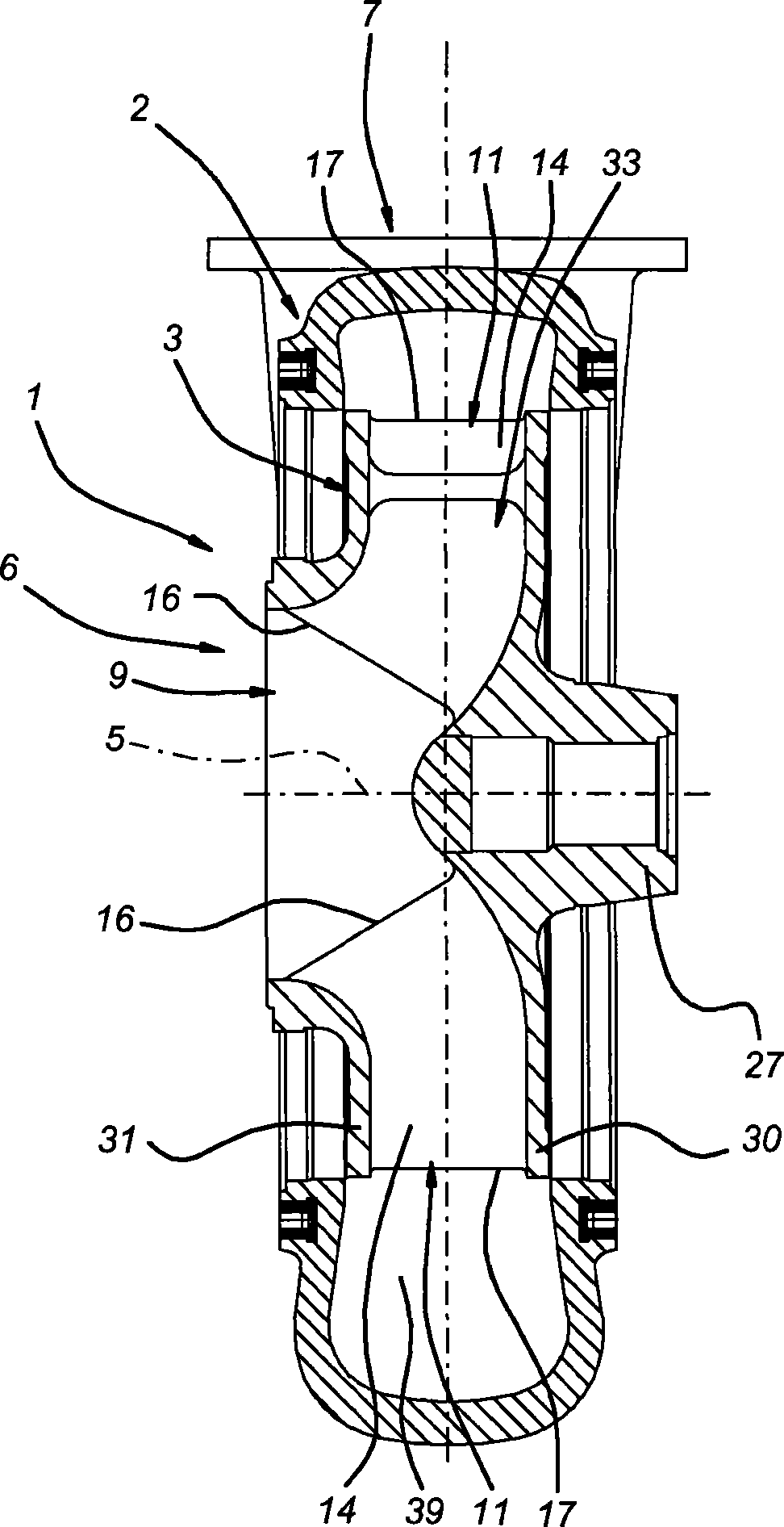
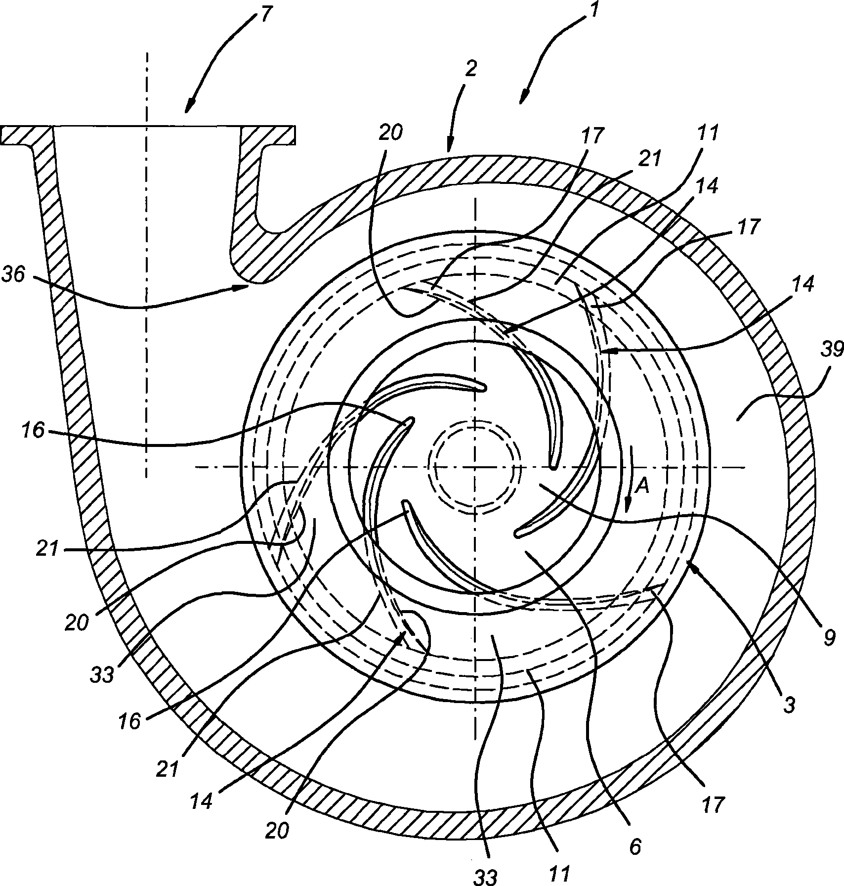
[0026] The centrifugal pump according to the invention is designated as a whole by the reference numeral 1 . The centrifugal pump 1 comprises a housing 2 which is helically shaped (see figure 2 ). The pump housing 2 comprises an axial inlet 6 and a tangential outlet 7 . The tangential outlet 7 is positioned transversely with respect to the housing 2 . In this exemplary embodiment, the tangential outlet 7 is designed as a nozzle. Furthermore, a rotor 3 is provided, which is arranged rotatably about an axial axis of rotation 5 within the housing 2 . The axial inlet 6 in the housing 2 is arranged centrally with respect to the rotor 3 .

[0027] The rotor 3 is usually formed from a single moulding. The rotor 3 comprises a hub 27 within which a shaft (not shown) mounted outside the housing 2 can be accommodated. The hub 27 defines the axis of rotation 5 of the rotor 3 . The rotor 3 further has a first wall or shaft housing 30 . The first wall 30 is connected to the hub 27 ...


PUM


Abstract

A centrifugal pump comprises a housing as well as a rotor which is arranged so as to be able to rotate about an axial axis of rotation in the housing. The rotor is provided with at least two rotor blades, each of which extends substantially radially with respect to the axis of rotation between a radial outer end and a radial inner end. The outer ends of at least two rotor blades are at radially different distances to the axis of rotation.

Description

technical field [0001] The invention relates to a centrifugal pump comprising a housing and a rotor arranged rotatably about an axial axis of rotation inside the housing, the rotor being provided with at least two rotor blades of which Each extends generally radially relative to the axis of rotation between a radially outer end and a radially inner end. Background technique [0002] Centrifugal pumps of this type are known. The casing of this centrifugal pump has an axial inlet and a tangential outlet. The rotor is provided with an axial supply or suction aligned with respect to the axial inlet of the housing, and a radial discharge. The rotor blades extend between a radially inner end and a radially outer end. The radial discharge is located between the outer ends of the rotor blades. [0003] During operation, the rotor rotates about an axial axis of rotation. Between the rotor blades, the mass to be pumped is forced radially outwards due to centrifugal force. The pu...

Claims


Application Information

Patent Timeline
Patent Type & Authority Applications(China)
IPC IPC(8): F04D29/24F04D29/22F04D29/66
CPCF04D29/242F04D29/2261F04D29/669
Inventor 哈桑·侯赛因·布达伊哲
Owner IHC荷兰知识产权有限公司
Why Eureka
Eureka Blog
Learn More