Illuminating light communication device

A technology of lighting optical communication and light quantity, applied in the field of communication services, can solve the problem of low transmission speed, etc., and achieve the effect of suppressing the variation of light quantity

Inactive Publication Date: 2009-05-13
NAKAGAWA LAB INC
View PDF1 Cites 62 Cited by
  • Summary
  • Abstract
  • Description
  • Claims
  • Application Information

AI Technical Summary

Problems solved by technology

However, when using illumination light for communication, although broadband communication can be performed in data transmission (downlink) from the illumination light communication device to each terminal, data transmission from each terminal (uplink) ) usually uses infrared communication, and the transmission speed is lower than that of the uplink
In this way, in communication using illuminating light, the communication speed is often asymmetrical, and from this point of view, it is problematic to still perform power line communication and illuminating light communication with the same protocol

Method used


Image

  • Illuminating light communication device
  • Illuminating light communication device

Examples


Embodiment Construction

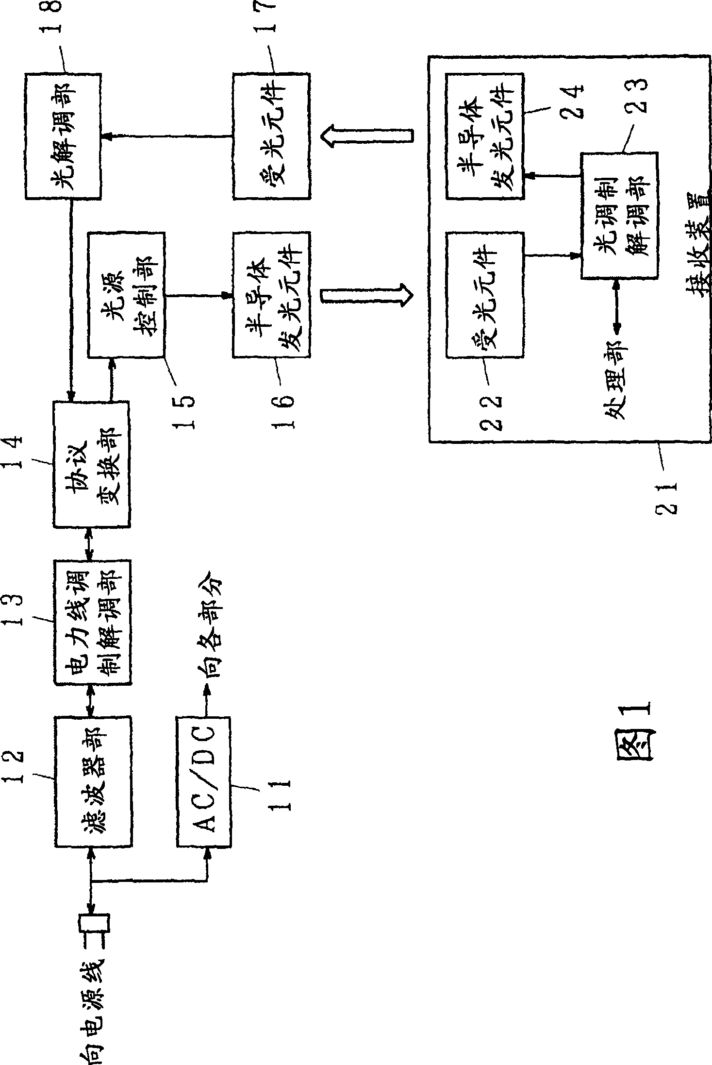
[0019] FIG. 1 is a block diagram of an example of a communication system including an embodiment of the present invention. In the figure, 11 is an AC / DC conversion part, 12 is a filter part; 13 is a power line modulation and demodulation part, 14 is a protocol conversion part, 15 is a light source control part, 16 is a semiconductor light emitting element, 17 is a light receiving element, and 18 is a 21 is a receiving device, 22 is a light receiving element, 23 is an optical modulation and demodulation unit, and 24 is a semiconductor light emitting element.

[0020] In the structure shown in FIG. 1 , the illuminating light communication device of the present invention is composed of an AC / DC conversion unit 11, a filter unit 12, a power line modulation and demodulation unit 13, a protocol conversion unit 14, a light source control unit 15, a semiconductor light emitting element 16, light receiving element 17, light demodulation unit 18, and the like. The AC / DC converter 11 co...


PUM


Abstract

An illuminating light communication device is provided to construct a communication system in which, when data are transmitted by using an electric power line and illuminating light, light intensity fluctuations of the illuminating light are suppressed and communication by means of the electric power line and the illuminating light can be well carried out. When data to be transmitted are sent through an electric power line, signal components are extracted in a filter (12), they are demodulated in an electric power line modulating unit (13), so that data are obtained. The obtained data are tentatively stored in a protocol converting unit (14). The data are then converted to an optical communication protocol, a semiconductor light emitting element (16) is turned on or off, or its light quantity is controlled to modulate illuminating light in accordance with data to be transmitted by a light source controller (15). Thus, the data are transmitted by making use of the illuminating light. As a modulation system for the light communication, multiple-value PPM may be used, wherein an existing pulse is set to OFF while a non-existing pulse is set to ON.

Description

technical field [0001] The present invention relates to a communication service for transmitting data using power lines and illuminating light (visible light). Background technique [0002] In recent years, semiconductor light emitting elements such as LEDs have been used as light sources for lighting. A semiconductor light-emitting element can perform high-speed blinking or light quantity control. Using this characteristic, a technology has been developed that transmits data using illumination light by flickering or controlling light intensity of semiconductor light emitting elements for illumination according to data. If the flickering of the semiconductor light-emitting element or the change in the light quantity is fast, the flickering or the change in the light quantity cannot be detected by human eyes. Therefore, it is possible to transmit data without hindering its use as illumination light for human beings. In addition, lighting devices are well-known devices, and...

Claims


Application Information

Patent Timeline
Patent Type & Authority Applications(China)
IPC IPC(8): H04B10/10H04B3/54H04B10/105H04B10/22H04B10/11H04B10/112H04B10/118
CPCH04B2203/5408H04B3/54H04B10/116H04B10/1143
Inventor 有田武美春山真一郎中川正雄山口武彦小峯敏彦
Owner NAKAGAWA LAB INC
Why Eureka
Try Eureka