Top butt-joint type oil rig headframe

A docking, oil technology, applied in drilling equipment, drill pipes, drill pipes, etc., can solve the problems of small moving length, safety accident of telescopic mechanism, large telescopic force, etc., and achieve flexible structure, high reliability, and installation force. small effect

Inactive Publication Date: 2009-05-20
RG PETRO MACHINERY GROUP
View PDF1 Cites 17 Cited by
  • Summary
  • Abstract
  • Description
  • Claims
  • Application Information

AI Technical Summary

Problems solved by technology

Compared with tower-shaped derricks and A-shaped derricks in other known technologies, this upright, no-guyline, front-opening, multi-section assembled derrick has the advantages of saving time and labor for installation, small installation space, and small moving length. Compared with the mast-shaped derrick, it does not need to use guy ropes to maintain stability, so it is advanced to a certain extent. However, the set section and bearing mechanism of this kind of derrick must bear all the weight of the upper and middle sections of the derrick itself and all drilling loads, that is, special equipment is required. The carrying mechanism
This kind of derrick adopts the structure that the bottom is docked with the middle section, and the upper section and all the docked middle sections are stretched together, so the telescopic force is very large, and the telescopic mechanism is prone to safety accidents. wire, even broken strands

Method used


Image

  • Top butt-joint type oil rig headframe
  • Top butt-joint type oil rig headframe
  • Top butt-joint type oil rig headframe

Examples


Embodiment Construction

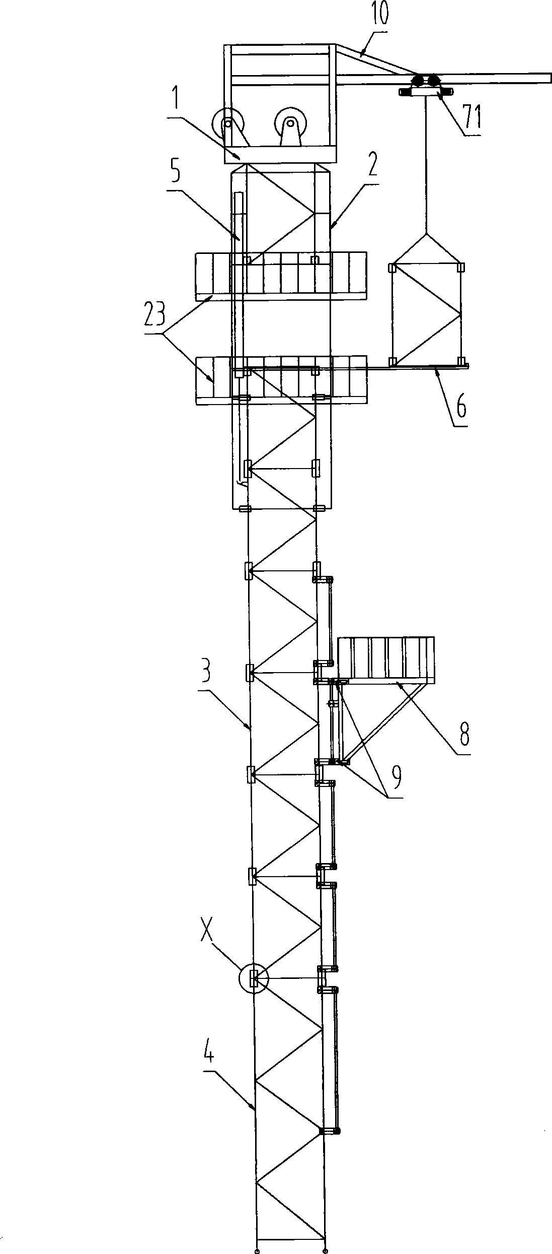
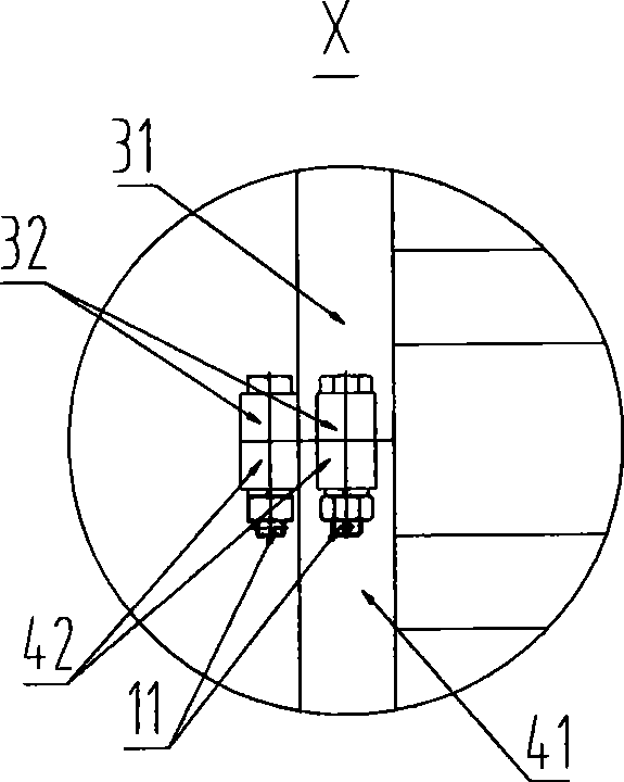
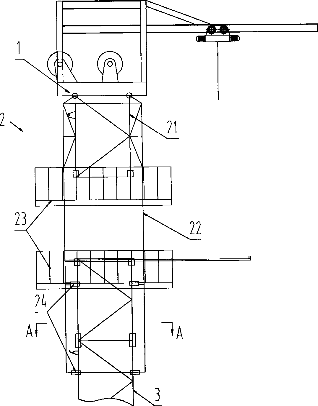
[0047] see first figure 1 , figure 2 , the derrick of the present invention is composed of crown block 1, upper section 2, several middle sections 3, lower section 4, upper telescopic mechanism 5, middle section movement and position limiting device 6, hoisting and transporting device, second-floor workbench 8, second-floor platform guiding movement and positioning Mechanism 9, crown block maintenance frame 10 and other necessary annexes of derrick such as working ladder, riser etc. are formed. The upper section 2, some middle sections 3, and the lower section 4 are all welded by four upright columns, diagonal braces, cross beams, and cross braces to form an upright, front-opening truss structure, and two side and one rear single-piece welded bolts in the known technology can also be used. Or pin-connected sub-assembly structure to facilitate transportation and hoisting. The lower section of the derrick can also be flexibly designed as a structure with a straight section at ...


PUM


Abstract

The invention relates to an overhead butting oil drill derrick which comprises an overhead travelling crane, an upper segment, a plurality of middle segments, a lower segment, an upper segment telescoping mechanism, a middle segment moving and limiting device, a lifting transportation device arranged on the maintenance rig of the overhead travelling crane, two layers of working table and the like. The upper segment, a plurality of middle segments and the lower segment all adopt an upright truss structure with the front being opened which is welded by four columns and a plurality of inclined struts, transverse beams and transverse bracings; and the lower segment, the plurality of middle segments and the upper segment respectively adopt a mode of aligning the head and the tail of the columns, contacting directly the end surfaces of the columns and passing through adapter sleeves arranged at the side surfaces of the columns, or connecting base plates by pin rolls or bolts. The butting of each segment of the derrick by bolts is realized at the top of space by the upper segment telescoping mechanism, the middle segment moving and limiting device and the lifting transportation device. The derrick has the characteristics of little and constant telescoping power when carrying out butting installation, light lifting weight, independent transportation of each segment, short moving length and adjustable butting height, and is especially applied in well fields with serious installation spaces of planes, or low requirements on module weight, or poor transportation conditions.

Description

technical field [0001] The invention relates to the technical field of oil drilling and repairing equipment, in particular to a top-jointed oil drilling rig derrick. Background technique [0002] In the known technology, the derrick of the oil drilling rig has an integral lifting type K-shaped derrick. Although the work stability is good and the wellhead is open, the lifting force is very large. The lifting force of the 4000m to 9000m common derrick reaches 80 tons to 300 tons. The risk is high, and the height of the derrick cannot be adjusted during operation, and the size is large during transportation. [0003] In the known technology, a derrick used for oil drilling and repairing equipment, patent number: ZL 00 2 03939.7, adopts an upright, no guy rope, front opening, multi-section assembled structure. According to the description of the utility model patent, it is composed of several derrick segments connected sequentially, including the upper section at the upper part...

Claims


Application Information

Patent Timeline
Patent Type & Authority Applications(China)
IPC IPC(8): E21B15/00E21B19/02
Inventor 何军国张勇余利军
Owner RG PETRO MACHINERY GROUP
Why Eureka
Try Eureka