Self-adapting pipe moving mechanism

A mobile mechanism and self-adaptive technology, which is applied in the direction of special pipes, pipe components, mechanical equipment, etc., can solve problems such as being stuck in the middle of the pipe, the robot cannot overcome obstacles, and rescue work is difficult, achieving the effect of strong adaptability

Inactive Publication Date: 2009-05-20
SHENYANG INST OF AUTOMATION - CHINESE ACAD OF SCI
View PDF0 Cites 46 Cited by
  • Summary
  • Abstract
  • Description
  • Claims
  • Application Information

AI Technical Summary

Problems solved by technology

Although this mechanism can realize forward and backward movement in the pipeline, when there are foreign objects or obstacles in the pipeline, the robot often cannot cross the obstacle
If there is no special protection, it is easy to get stuck...

Method used


Image

  • Self-adapting pipe moving mechanism
  • Self-adapting pipe moving mechanism
  • Self-adapting pipe moving mechanism

Examples


Embodiment 1

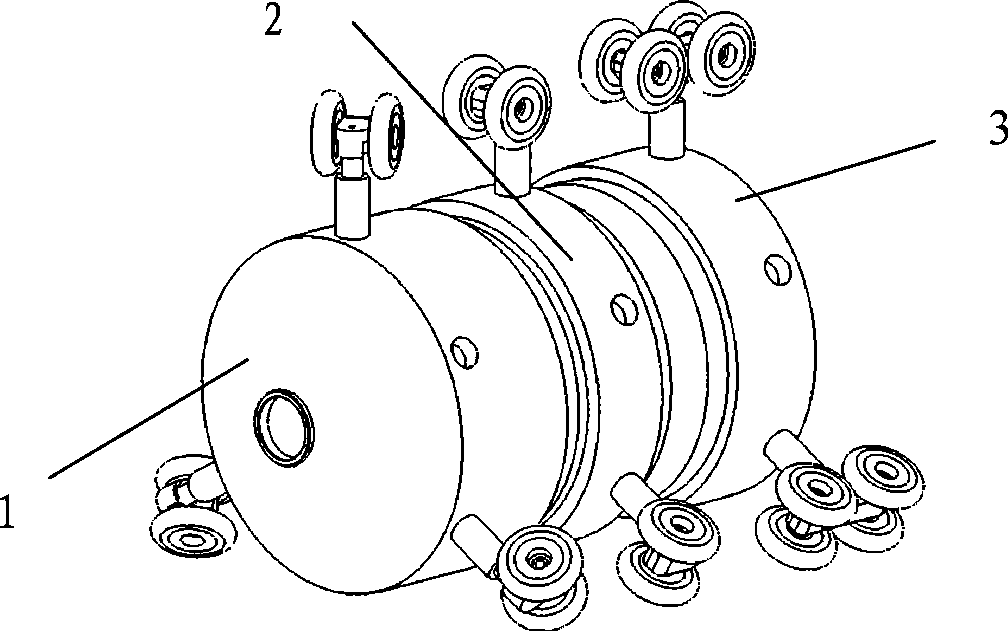
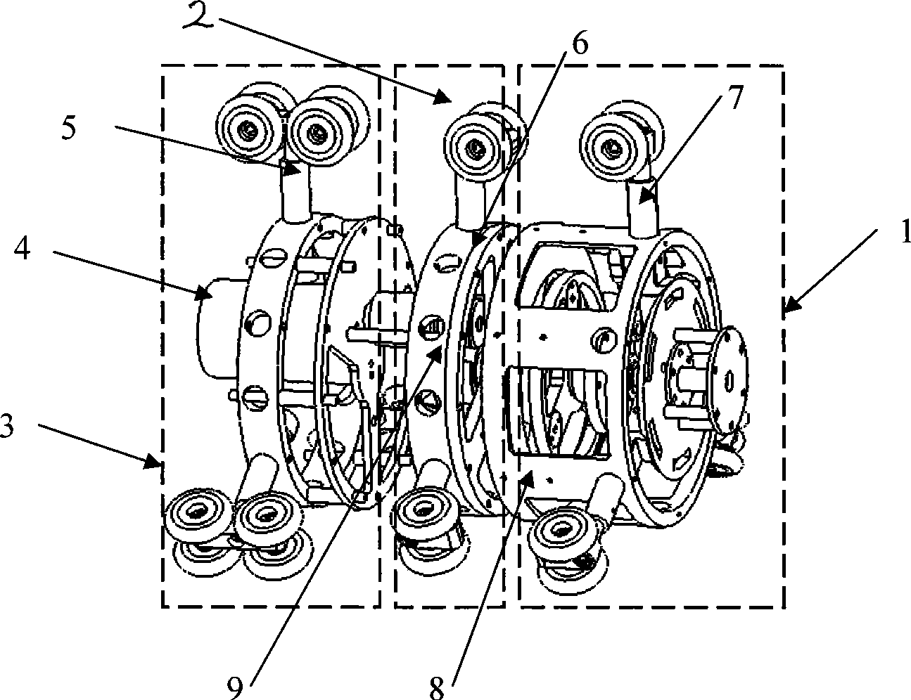
[0015] Embodiment 1: as figure 1 , figure 2 As shown, the structure of the present invention includes three parts: a forward drive mechanism, a reverse drive mechanism and a support mechanism. The forward drive mechanism is connected with the reverse drive mechanism through the first transmission mechanism, and connected with the motor in the support mechanism through the second transmission mechanism. A locking mechanism and a linkage mechanism are also installed between the forward driving mechanism and the first transmission mechanism.

[0016] Such as figure 2 As shown, wherein said forward drive mechanism 1 comprises a front wheel frame 8, three forward drive arms 7 uniformly distributed along its circumference, 2 driven wheels installed on each forward drive arm, the rolling of said driven wheels The axis and the pipe section form an angle of 0 to 45 degrees. The backward driving mechanism 2 includes a rear wheel frame 9, three backward driving arms 6 uniformly dist...

Embodiment 2

[0020] Embodiment 2: the moving mechanism of this example is identical in structure with embodiment 1, and the difference is: in the forward driving mechanism 1, the forward driving arm 7 is evenly distributed along the circumference of the front wheel frame 8, and the driven wheels on each forward driving arm 7 are 1 piece; 5 backward driving arms 6 are evenly distributed along the circumference of the rear wheel frame in the backward driving mechanism 2, and there are 2 driven wheels for each backward driving arm 6; in the supporting mechanism 3, the supporting arms 5 are evenly distributed along the outer frame circumference of the supporting mechanism 6, the support wheels of each support arm 5 are 2.

Embodiment 3

[0021] Embodiment 3: the moving mechanism of this example is identical in structure with embodiment 1, and the difference is: in the forward driving mechanism 1, the forward drive arm 7 is evenly distributed along the circumference of the front wheel frame 8, and the driven wheels on each forward drive arm 7 are 2 pieces; in the backward driving mechanism 2, six backward driving arms 6 are evenly distributed along the circumference of the rear wheel frame, and each driven wheel of the backward driving arm 6 is 2; in the supporting mechanism 3, the supporting arms 5 are evenly distributed along the outer frame circumference of the supporting mechanism 6, the support wheels of each support arm 5 are 4.


PUM


Abstract

The invention provides a self-adaptive pipeline moving mechanism, which belongs to the technical field of pipeline robot engineering. The structure of the mechanism comprises a supporting mechanism, a forward drive mechanism and a backward drive mechanism, wherein the forward drive mechanism is connected with the backward drive mechanism through a first transmission mechanism, and is connected with a motor in the supporting mechanism through a second transmission mechanism; the first transmission mechanism is arranged in the forward drive mechanism; and a link mechanism and a locking mechanism are arranged between the forward drive mechanism and the first transmission mechanism. The mechanism can automatically regulate forward and backward in the pipeline without external control. In the invention, when a forward drive arm is contracted because of a barrier, other forward drive arms are also contracted to the center through linkage of the link mechanism, thereby realizing synchronous motion of the drive arms. Meanwhile, the locking mechanism restricts the rotation of the forward drive arms, at this time the route of power output is converted, and backward drive arms rotate and generate backward driving force, namely a robot moves towards an opposite direction. The moving mechanism has strong adaptability.

Description

technical field [0001] The invention belongs to the technical field of pipeline robot engineering, and in particular relates to an adaptive pipeline moving mechanism for exploration operations in pipelines. Background technique [0002] With the development of economy and society, pipelines, as the main fluid (natural gas, oil, water, etc.) transportation tools, have been widely used because of their convenience and economy. However, as the service life increases, the pipeline will inevitably age, corrode or be damaged by external construction. If it is not dealt with in time, once an accident occurs, it will not only bring huge economic losses to the country, but also cause serious pollution to the environment. Therefore, regular inspection and maintenance of pipelines is very necessary. A pipeline inspection robot is an effective device for inspecting pipelines. At present, the movement forms of the in-pipe walking mechanism used for pipeline detection robots mainly inc...

Claims


Application Information

Patent Timeline
IPC IPC(8): F16L55/32F16L101/30
Inventor 马书根李斌李鹏叶长龙龚海里张国伟
Owner SHENYANG INST OF AUTOMATION - CHINESE ACAD OF SCI
Why Eureka
Try Eureka