Camera

A camera and shutter technology, applied in the field of cameras, can solve the problems of long delay and time-consuming ranging, and achieve the effect of shortening the delay and high-speed driving.

Active Publication Date: 2009-05-20
奥之心数字科技株式会社
View PDF1 Cites 5 Cited by
  • Summary
  • Abstract
  • Description
  • Claims
  • Application Information

AI Technical Summary

Problems solved by technology

[0006] In this way, when TTL phase difference AF is performed on the live view display, the movable mirror must be lowered and raised before and after it, and distance measurement takes time.
That is, in a camera having two states of the first photographing preparation state with the shutter closed (such as an observation state

Method used


Image

  • Camera
  • Camera
  • Camera

Examples


Example Embodiment

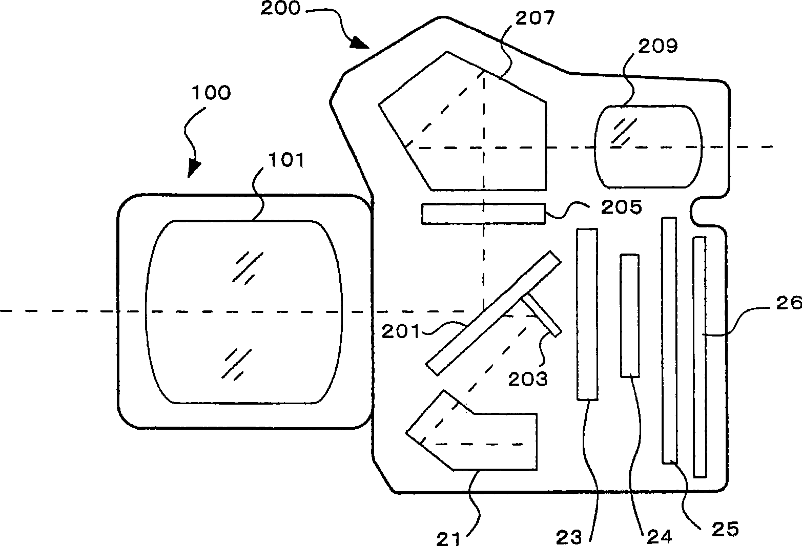
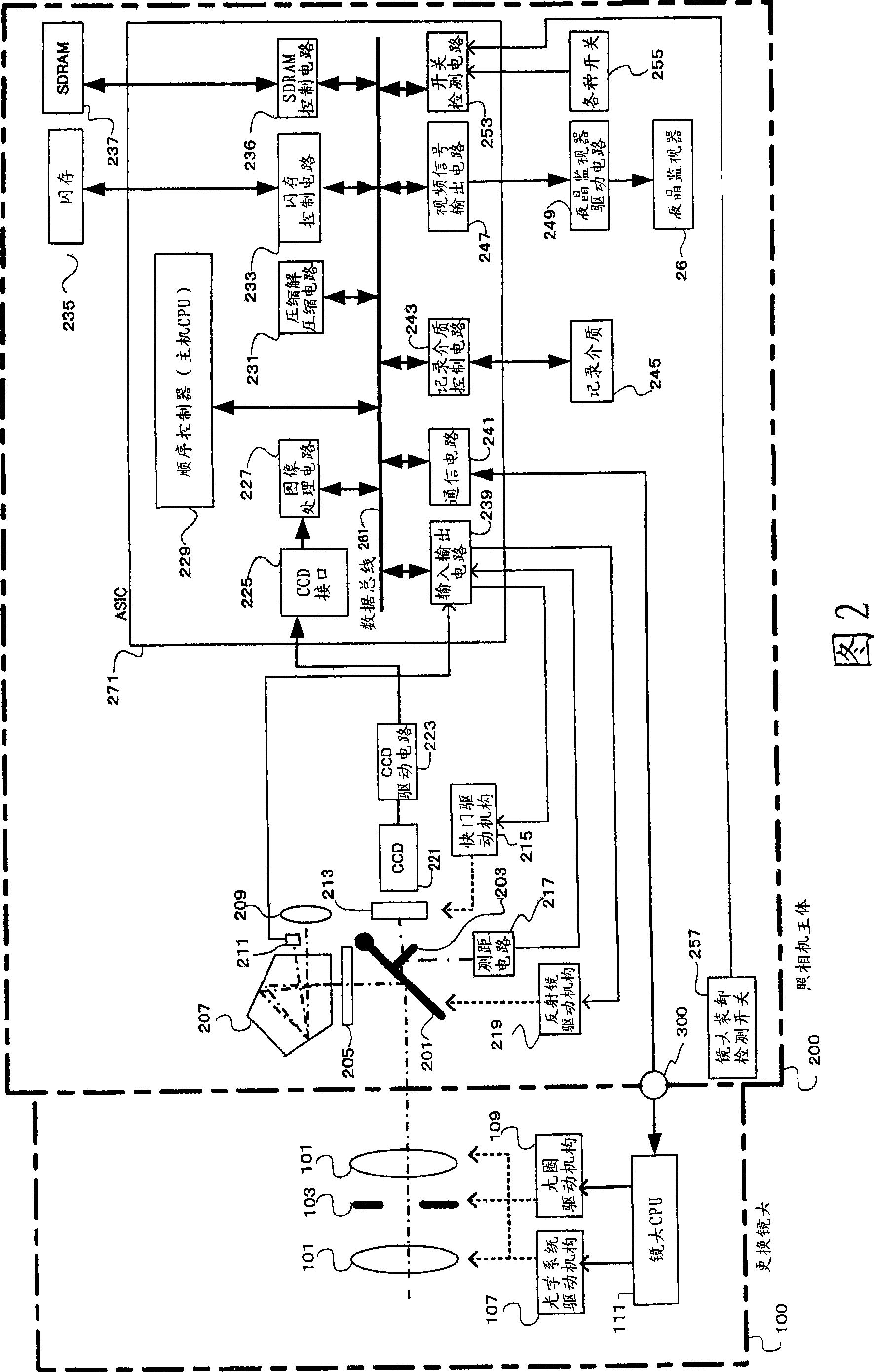
[0027] Hereinafter, a preferred embodiment using a digital single-lens reflex camera to which the present invention is applied will be described based on the drawings. figure 1 It is a block diagram of the internal structure along the optical axis direction of the photographic lens in the internal structure of the digital single-lens reflex camera according to an embodiment of the present invention.

[0028] A movable mirror 201 is arranged in the mirror box of the camera body 200 on the optical axis of the photographic optical system 101 arranged inside the interchangeable lens 100. The movable mirror 201 can be rotated between a reflecting position and a retracted position. The reflecting position is inclined 45 degrees with respect to the optical axis of the photographic optical system 101 in order to reflect the subject light beam to a viewfinder optical system such as a pentaprism 207. The retreat position is a position retreated from the imaging optical path in order to gui...


PUM


Abstract

The invention provides a camera which can be driven in a high speed and shorten time delay in the case of carrying out shutter action in a second shooting preparation state such as the live view display. When the camera is in a live view display state, the magnet adsorption (S5) in the shutter first curtain is relieved, thus allowing the shutter first curtain to move and carrying out live view display (S7) according to the output from CCD221; in such moment, shutter rear curtain keeps in a connection (absorption) state, and the shutter is in an open state. The AF switch is put through (S11), and the shutter rear curtain also keeps in an open state when the phase separation AF based on TTL measuring distance, thus reducing the tight load on the shutter and shortening time delay.

Description

technical field [0001] The present invention relates to a camera, and more specifically, to a camera having two states of a first shooting preparation state with a shutter closed and a second shooting preparation state with the shutter open. Background technique [0002] In recent years, cameras having a live view display function have been known. For example, Patent Document 1 discloses a digital single-lens reflex camera capable of live view in which the movable mirror is retracted from the photographing optical path and the focal plane shutter is fully opened. Next, the subject image is imported into the imaging element, and the obtained subject image is continuously displayed on the LCD monitor. In the camera disclosed in this patent document 1, when the focus switch is turned on, a movable mirror is inserted into the imaging optical path, and the focus shift amount is detected by so-called TTL phase difference AF, and the focus shift amount is determined based on the fo...

Claims


Application Information

Patent Timeline
IPC IPC(8): G03B19/12G03B9/08H04N5/225
Inventor 寺田洋志
Owner 奥之心数字科技株式会社
Why Eureka
Try Eureka