Ratcheting tensioner with a sliding and pivoting pawl
A technology of tensioner and pawl, applied in the direction of belt/chain/gear, transmission device, mechanical equipment, etc.
- Summary
- Abstract
- Description
- Claims
- Application Information
AI Technical Summary
Problems solved by technology
Method used
Image
Examples
Embodiment Construction
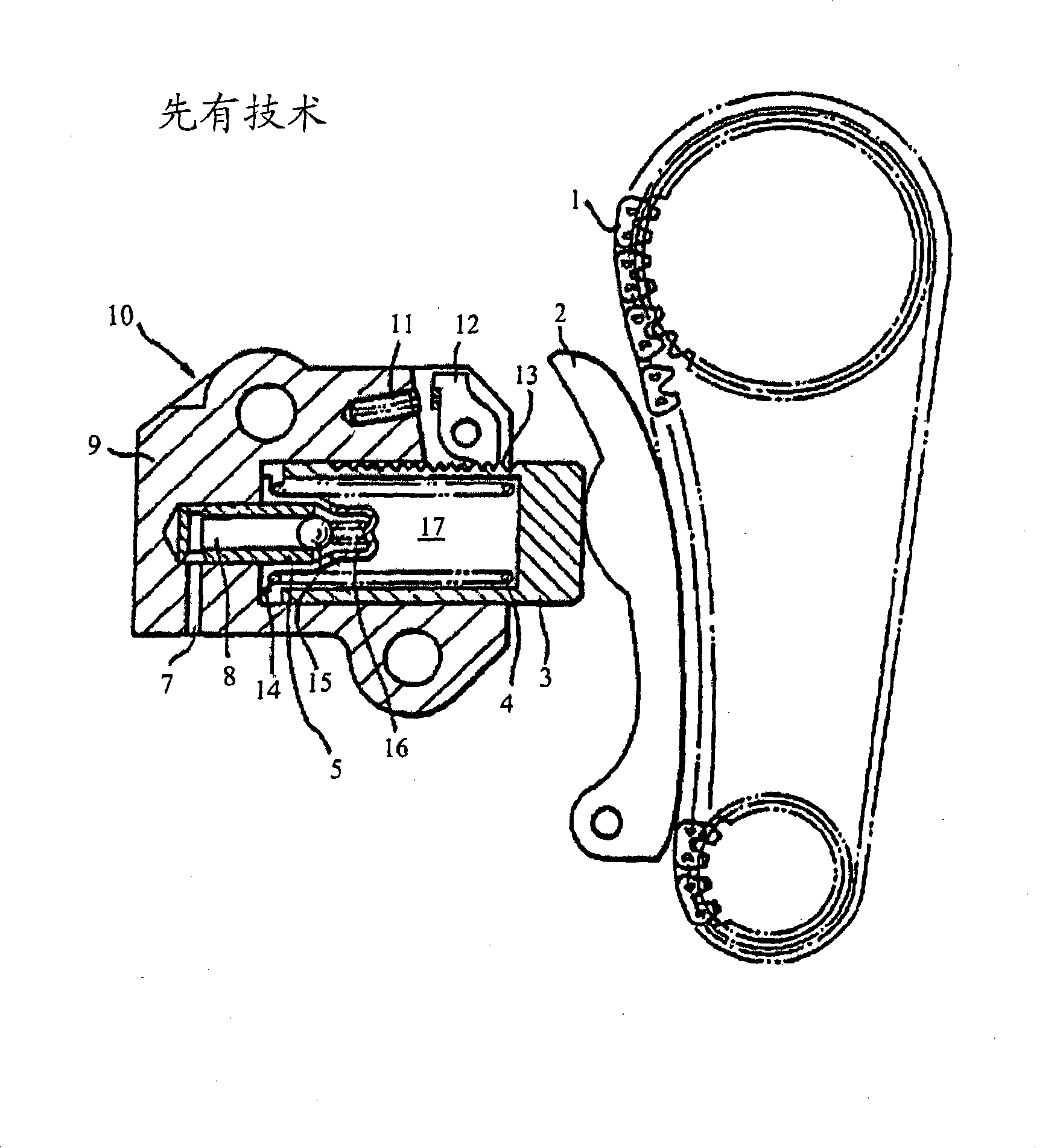
[0029] Figures 5 to 13 shows the tensioner of the present invention. The tensioner includes a housing 202 having a cutout 228 for receiving a rotating, sliding pawl 206, and a bore 216 for slidingly receiving a hollow piston 204 that creates a fluid flow with the bore 216. Room 219. A passage 224 inside the housing 202 connects a source of pressurized fluid to the fluid chamber 219 . A check valve 221 comprising a flow ball 220 and a seat 222 only allows fluid to flow into the fluid chamber 219 . Piston 204 is biased by spring 218 in a protruding direction from housing 202 towards a chain or belt (not shown). The piston 204 includes a series of slots 204b around or through at least a portion of the outer circumference of the piston 204 for ratcheting engagement with a rotationally sliding pawl 206 . At least one of these grooves acts as a stop 204d to help prevent the piston 204 from being ejected from the housing 202 .
[0030] The rotating, sliding pawl 206 is rotatabl...
PUM
 Abstract
Description
Claims
Application Information
 - R&D
- Intellectual Property
- Life Sciences
- Materials
- Tech Scout
- Unparalleled Data Quality
- Higher Quality Content
- 60% Fewer Hallucinations
Browse by: Latest US Patents, China's latest patents, Technical Efficacy Thesaurus, Application Domain, Technology Topic, Popular Technical Reports.
© 2025 PatSnap. All rights reserved.Legal|Privacy policy|Modern Slavery Act Transparency Statement|Sitemap|About US| Contact US: help@patsnap.com


