Tappet rod for operating switch element

A technology for manipulating switches and switching elements, which is applied in the direction of electric switches, electrical components, contact operating parts, etc., and can solve the problems of damaged, destroyed, and small sizes of sealing devices, and achieve the effect of preventing collisions and avoiding corrosion

A technology for manipulating switches and switching elements, which is applied in the direction of electric switches, electrical components, contact operating parts, etc., and can solve the problems of damaged, destroyed, and small sizes of sealing devices, and achieve the effect of preventing collisions and avoiding corrosion

CN101438362AActive Publication Date: 2009-05-20SIEMENS AG

Image

  • Tappet rod for operating switch element
  • Tappet rod for operating switch element
  • Tappet rod for operating switch element

Examples


Embodiment Construction

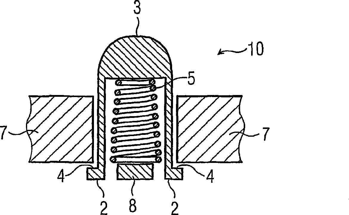
[0028] figure 1 Shown is a cross-sectional view of a first embodiment of a lifter 10 in an installed state. The tappet 10 shown comprises an elastic element 5 embodied as a pressure spring, an actuation zone 3 for actuating the tappet 10 by an operating head (not shown), and for actuating the switching unit or the switch unit by the tappet 10 . Active surface 2 on which switching element 1 is actuated. The direction of actuation of the tappet 10 is directed from top to bottom. The above-mentioned elastic element 5 abuts both on the blocking device 8 and on the inner side of the above-mentioned tappet 10 . The tappet 10 is in an unactuated starting state (basic position). That is to say, the restoring force action of the spring element 5 is transmitted by the stop 4 to the holder 7 of the housing. When the tappet 10 is manipulated through the manipulation zone 3 , the elastic element 5 is compressed, and the restoring force is transmitted to the manipulation element (not sh...


PUM


Abstract

The invention relates to a tappet for actuating a switching element, especially for using in a position switch or a safety switch, said tappet comprising at least one abutment for pre-tensioning by means of at least one elastic element. Until now, the insertion of such a tappet inside a switch had lead to spatial requirements inside the switch. The inventive tappet comprises an inner region for at least partially receiving the elastic element, freeing the space around the tappet for other components. Furthermore, the invention also provides a simpler assembly and a way of advantageously protecting the elastic element.

Description

technical field [0001] The invention relates to a tappet for actuating a switching element, wherein the tappet has at least one stop for generating a prestressing force against the actuation direction by means of at least one elastic element. Furthermore, the invention relates to a switch, in particular a position switch or a safety switch, having at least one switching element and at least one tappet of the type mentioned in the opening paragraph for actuating the switching element. Background technique [0002] This type of tappet or switch is used in electromechanical switching devices. For example in position switches or safety switches. [0003] Electromechanical switching devices are used to monitor protective devices, such as safety gates or protective barriers, as well as to monitor the movement of machine parts. A switch of this type or the tappet contained therein can in principle be used wherever one or more switching elements are actuated by an actuating moveme...

Claims


Application Information

Patent Timeline
20 May 2009
Publication
CN101438362A
IPC
H01H13/14; H01H3/12
CPC
H01H3/12; H01H13/18; H01H2229/042; H01H13/186; H01H13/14
Inventors
沃纳·普里; 乔基姆·塞德尔