
Touching temporal gain compensated control device and method for ultrasonic diagnostic device

A technology of time gain compensation and ultrasonic diagnostic instrument, which is applied in ultrasonic/sonic/infrasonic diagnosis, acoustic diagnosis, infrasonic diagnosis, etc. It can solve the problems of large space occupation, design obstacles of portable products, and inconvenient and natural operability, etc. Convenience, saving and analog-to-digital converter, high reliability effect

Inactive Publication Date: 2009-05-27
SHENZHEN MINDRAY BIO MEDICAL ELECTRONICS CO LTD
View PDF4 Cites 13 Cited by
  • Summary
  • Abstract
  • Description
  • Claims
  • Application Information

AI Technical Summary

Problems solved by technology

[0005] 1. The existing time gain compensation device is mainly affected by the size of the sliding potentiometer, which occupies a large space and brings obstacles to the design of portable products;
[0006] 2. The operability is not convenient and natural enough, it is necessary to move the sliding rod of the sliding potentiometer to the predetermined position

Method used


Image

  • Touching temporal gain compensated control device and method for ultrasonic diagnostic device
  • Touching temporal gain compensated control device and method for ultrasonic diagnostic device
  • Touching temporal gain compensated control device and method for ultrasonic diagnostic device

Examples


Embodiment Construction

[0030] In this embodiment, the design of an ultra-thin time gain compensation (TGC) device is mainly realized by using a touch sensing device.

[0031] Figure 4 It is the functional block diagram of the touch TGC module, which is mainly composed of a touch sensor and a corresponding processor. The touch sensor is mainly used to sense finger movements such as touching, removing, and sliding; the processor mainly processes the output signal of the touch sensor, and transmits it to the host computer after real-time processing.

[0032] Figure 5 The structural block diagram of the control device of the touch TGC module is given, which mainly consists of the following four parts:

[0033] (1) Surface film 51, which is made of insulating and wear-resistant material, is mainly used to protect the touch sensor, and there is a silk screen on it to indicate the TGC touch area;

[0034] (2) touch sensor 52, which can be a one-dimensional strip sensor or a two-dimensional sensor surf...


PUM


Abstract

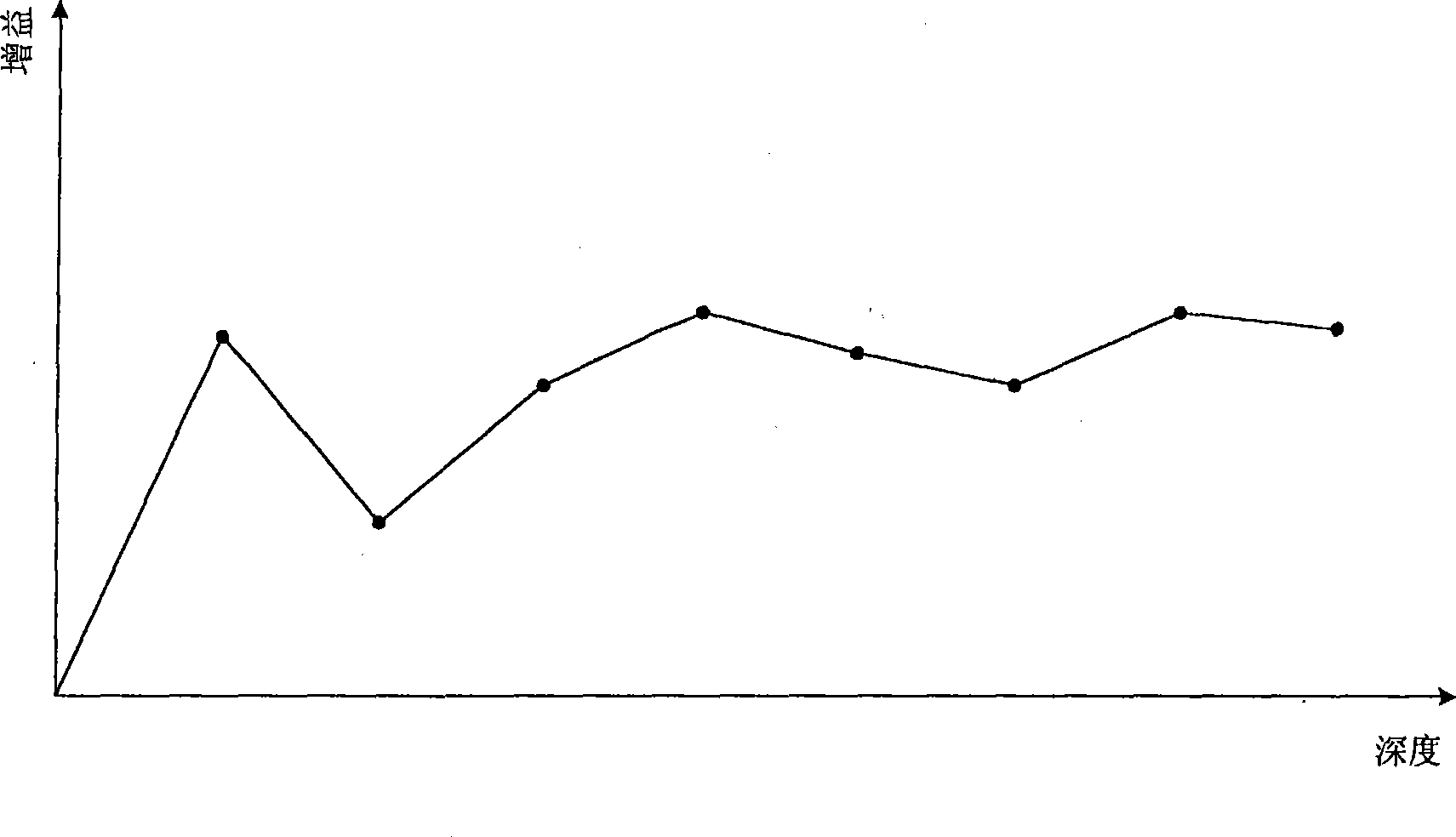
The invention discloses a touch time gain compensation control apparatus used in an ultrasonic diagnostic apparatus and a hand-slip type time gain compensation curve setting method. The touch time gain compensation control apparatus comprises a touch inductor used for inducing touch action and a processor which is used for processing an output signal from the touch inductor and sending the processed signal to a host computer. The method comprises the steps as follows: a finger slips over a touch area of a touch time gain compensation device; the touch inductor identifies the slipped position by the finger and outputs a single corresponding to the position; the processor processes the signal from the touch inductor and sends the processed signal to the host computer; and the host computer draws a time gain compensation curve according to the received signal. The touch time gain compensation device and the time gain compensation curve setting method provided by the embodiment of the invention have low cost, high reliability and convenient operation.

Description

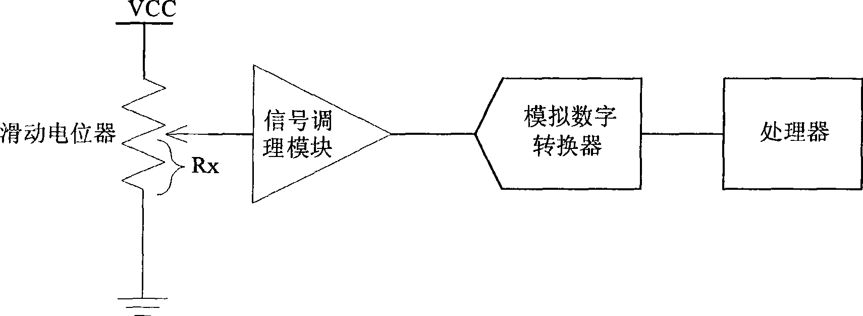
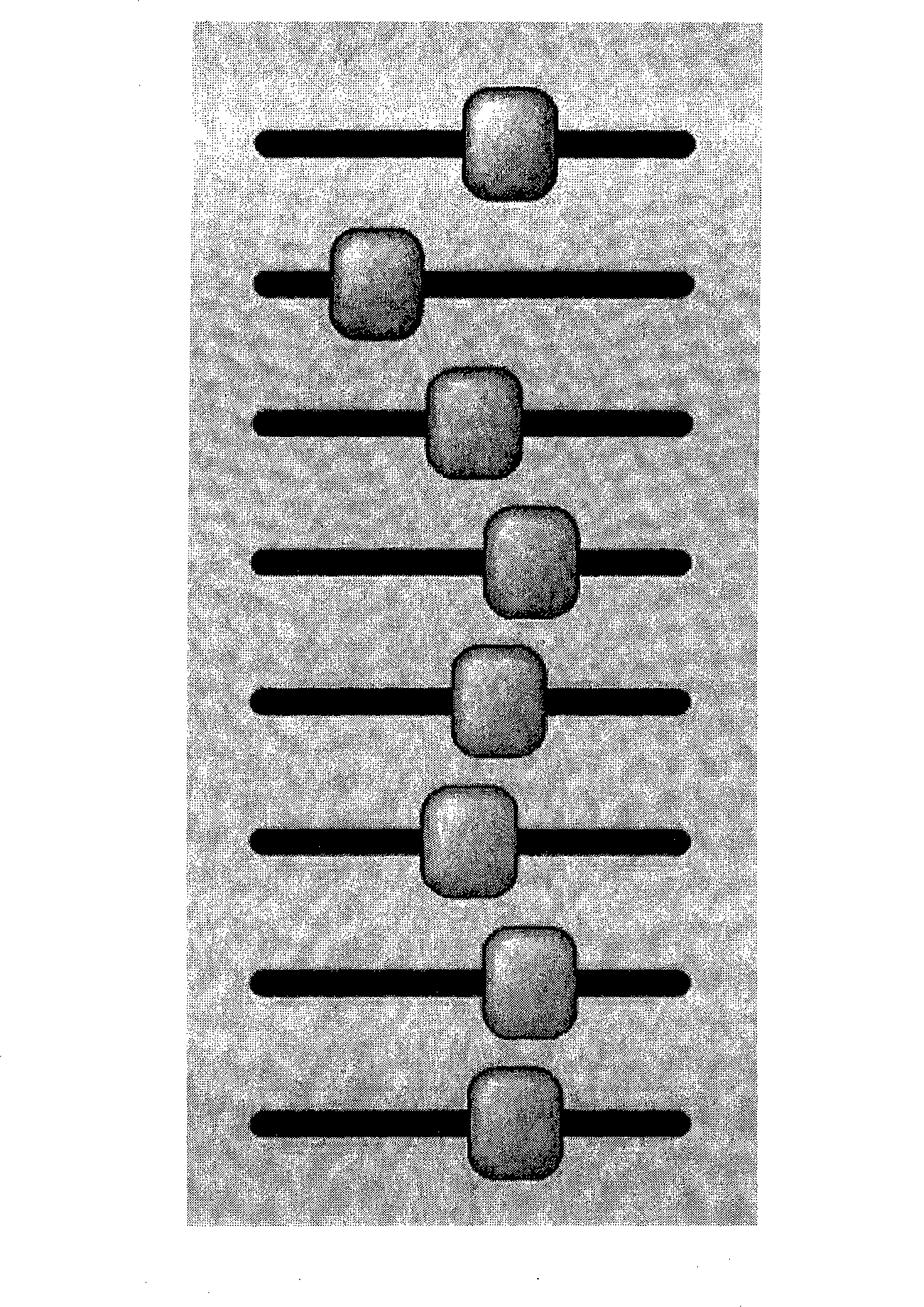
technical field [0001] The invention relates to a time gain compensation device and a time gain compensation curve setting method, in particular to a touch-type time gain compensation control device and a time gain compensation curve setting method for an ultrasonic diagnostic instrument. Background technique [0002] Time Gain Compensation (TGC) device is one of the important components of ultrasonic diagnostic equipment. In the prior art, a slide potentiometer (slide potentiometer) is used to realize the TGC device, wherein the block diagram of each segment of TGC is as follows figure 1 . figure 2 It is the appearance diagram of eight-segment TGC, which uses 8 sliding potentiometers. When the slider of the sliding potentiometer is at the bottom end (that is, the GND terminal), its output voltage is almost zero; when the slider is at the top end (that is, the VCC terminal), its output voltage is VCC. Assuming that the total resistance value of the sliding potentiometer ...

Claims


Application Information

Patent Timeline
Patent Type & Authority Applications(China)
IPC IPC(8): A61B8/00
Inventor 关智勇刘照泉
Owner SHENZHEN MINDRAY BIO MEDICAL ELECTRONICS CO LTD
Learn More