Filter device

A filter and filter surface technology, applied in chemical instruments and methods, household heating, heating methods, etc., can solve the problems of small filter surface inclination, unreliable grease, dripping on the stove, etc.

Active Publication Date: 2009-05-27
BSH BOSCH & SIEMENS HAUSGERAETE GMBH
View PDF5 Cites 7 Cited by
  • Summary
  • Abstract
  • Description
  • Claims
  • Application Information

AI Technical Summary

Problems solved by technology

[0003] The disadvantage of this filter arrangement is that the slope of the filter surface is too small, so

Method used


Image

  • Filter device
  • Filter device
  • Filter device

Examples


Embodiment Construction

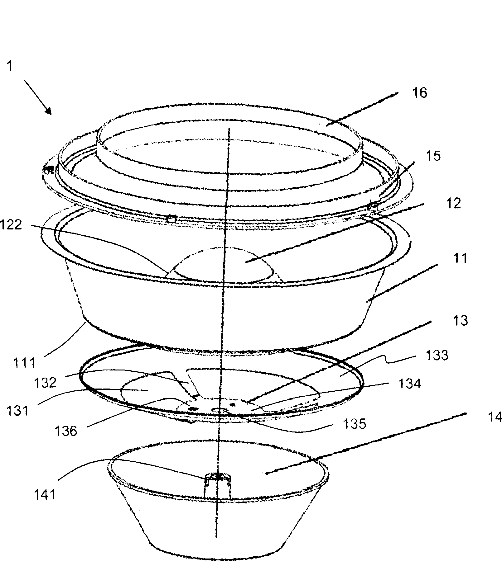
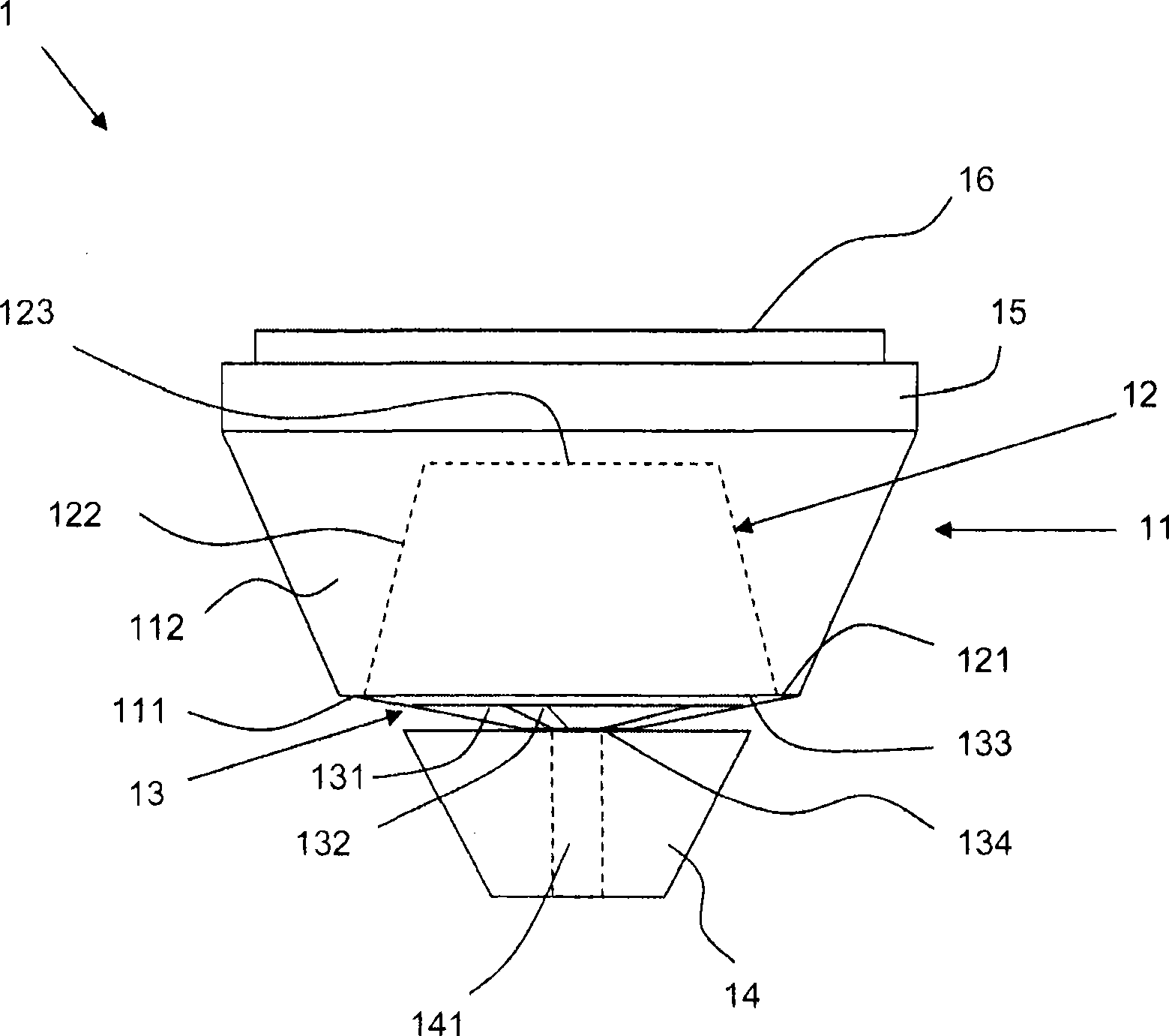
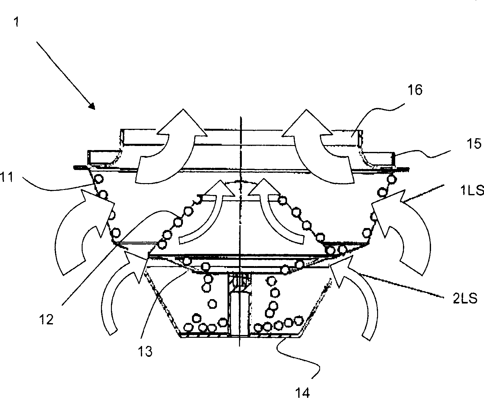
[0035] figure 1 An exploded schematic view of an embodiment of the filter device 1 according to the invention is shown. The filter device 1 comprises an outer first filter element 11 , an inner second filter element 12 and a collection container 14 arranged below the filter elements 11 , 12 . Between the collection container 14 and the filter elements 11 , 12 a base plate 13 is arranged as a discharge device. A connecting ring 15 is arranged above the first filter element 11 . The filter element 11 can be connected to a smoke extraction hood (not shown) via this connecting ring. An inflow nozzle 16 is arranged in the connection ring 15 . Through these nozzles air can flow from the filter device 1 into the interior of the smoke extraction hood. Air is sucked through the filter device 1 into the smoke extraction hood by a fan in the smoke extraction hood.

[0036] In the embodiment shown, the filter surface 112 of the first filter element 11 has the shape of a truncated con...


PUM


Abstract

The invention relates to a filtration unit for kitchen extraction hood, comprising a first filter element (11) and a collecting container (14) provided under the first filter element (11); wherein the filter face (112) of the first filter element (11) is a housing shrinking downwards; lower edge (111) of the first filter element (11) is a drain region; and the filter face (112) is a first intake region. The filtration unit is characterized that the filtration unit (1) includes a second intake region (131) separated from the first intake region by the drain region (111).

Description

technical field [0001] The invention relates to a filter device for a smoke extraction hood. Background technique [0002] In the smoke extraction hood, the filter device serves in particular to separate dirt, in particular grease particles, from the smoke drawn in through the smoke extraction hood. Usually used on the cooktop are some obliquely extending from the horizontal line, especially conical grease filter devices, where the steam or boiled steam on the cooktop mainly contains thin liquid and non-resinous grease, such as vegetable oil. The grease separated from the smoke in these devices, or the collected liquid, is discharged downwards supported by the adhesive force and collected there in a collection container. Such a filter arrangement is described, for example, in DE 197 53 687 A1 and DE 10 2005 019 831 A1. [0003] A disadvantage of this filter arrangement is that the slope of the filter surface is too low, so that the separated grease cannot flow reliably in...

Claims


Application Information

Patent Timeline
IPC IPC(8): B01D45/08F24C15/20
CPCF24C15/2035
Inventor E·费斯塔梅尔B·马克
Owner BSH BOSCH & SIEMENS HAUSGERAETE GMBH
Why Eureka
Try Eureka