
Main transmission spindle for three-roller tandem rolling tube machine

A main drive and continuous rolling technology, which is applied in the driving device of metal rolling mill, metal rolling, metal rolling, etc., can solve the problem of fast production rhythm of continuous rolling mill, increased output, unstable connection between shaft and roll , affecting the production rhythm of equipment, etc., to achieve the effect of improving work stability, shortening roll change time, and ensuring production rhythm

Active Publication Date: 2009-05-27
TAIYUAN HEAVY IND
View PDF0 Cites 9 Cited by
  • Summary
  • Abstract
  • Description
  • Claims
  • Application Information

AI Technical Summary

Problems solved by technology

In the high-speed state, the connection between the connecting shaft and the roll is unstable. At the same time, the time for changing the roll of this connecting shaft is long, which affects the production rhythm of the equipment.
The shaft joints of the existing technology cannot meet the requirements of the current continuous rolling mill for faster production rhythm and higher output.

Method used


Image

  • Main transmission spindle for three-roller tandem rolling tube machine
  • Main transmission spindle for three-roller tandem rolling tube machine
  • Main transmission spindle for three-roller tandem rolling tube machine

Examples


Embodiment Construction

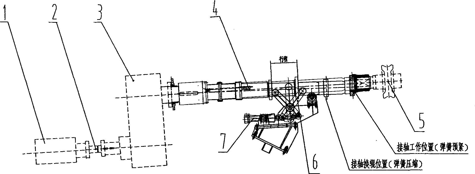
[0012] like image 3 As shown, a main drive connecting shaft for a three-roll continuous rolling mill is to connect the movable spline shaft 4-1 and the inner spline sleeve 4-3 with a flange 4-4 to form a sliding assembly. The fixed spline shaft 4-5 is arranged inside, and the spring 4-2 is installed between the fixed spline shaft 4-5 and the sliding assembly, and the spline on the fixed spline shaft completes the function of connecting the shaft to expand and contract. Spring 4-2 is made up of two identical springs, one is installed in the cavity of movable spline shaft 4-1, and the other is installed on the fixed spline shaft 4-5, and spacer ring 4-5 is arranged between two springs. 8. Play a supporting role. Add supporting studs 4-7 at the working position of the connecting shaft, and the supporting studs will fix the position of the moving spline shaft in the working position of the connecting shaft, so as to ensure that the connecting shaft will not come out when it is r...


PUM


Abstract

A main transmission connecting shaft for a three-roller continuous tube rolling mill relates to a production device of a seamless steel pipe. The invention mainly solves the problem in the prior art that roll change time of the connecting shaft is longer and unstable production factors exist so that the production rhythm of the device is affected. A movable spline shaft and an internal spline housing are connected into a sliding component by a flange; a fixed spline shaft is arranged in the sliding component; a spring is mounted between the fixed spline shaft and the sliding component; and a supporting stud is additionally arranged in the working position of the connecting shaft. The main transmission connecting shaft improves the work stability of the connecting shaft in the high-speed state, shortens the roll change time of the continuous tube rolling mill, ensures the production rhythm of the device and improves the output.

Description

technical field [0001] The invention relates to seamless steel pipe production equipment, in particular to the connecting shaft of the main transmission device of the three-roll continuous rolling pipe. Background technique [0002] The three-roll rolling mill is the most important equipment in the production of seamless steel pipes and the main process of metal deformation, and the main transmission device of the three-roll rolling mill is the power guarantee for metal deformation. The function of the main transmission device in the three-roller continuous pipe rolling unit is to reasonably transmit the power of the motor to the main machine according to the requirements of metal deformation. The power transmission process is attached figure 1 The main motor 1 drives the speed reducer 3 through the safety coupling 2, and the speed reducer drives the main transmission connecting shaft 4, and the connecting shaft connects the roll 5 of the rolling mill, thereby realizing the...

Claims


Application Information

Patent Timeline
Patent Type & Authority Applications(China)
IPC IPC(8): B21B35/14
Inventor 史敏刘润林
Owner TAIYUAN HEAVY IND
Learn More