Machine tool liquid kinetic pressure center frame

A technology of hydrodynamic pressure and steady rest, which is applied in grinding machines, machine tools designed for grinding workpiece rotating surfaces, grinding workpiece supports, etc., which can solve the problems of poor ability to absorb vibration of workpieces, easily damaged machined surface quality, and support accuracy No high problems, to achieve the effect of absorption and vibration, high support precision, and vibration suppression

Inactive Publication Date: 2009-05-27
HEFEI UNIV OF TECH
View PDF4 Cites 10 Cited by
  • Summary
  • Abstract
  • Description
  • Claims
  • Application Information

AI Technical Summary

Problems solved by technology

Due to the rigid contact support of the existing steady rest or tool rest, there are the following deficiencies: the ability to absorb the vibration of the workpiece is poor, and even the additional vibration of the workpiece is generated, especially when the workpiece rotates at a high speed; Continuous oil lubrication; when the machining accuracy is high, direct contact is easy to damage the machined surface quality of the machined parts; the support accuracy is not high

Method used


Image

  • Machine tool liquid kinetic pressure center frame
  • Machine tool liquid kinetic pressure center frame
  • Machine tool liquid kinetic pressure center frame

Examples


Embodiment 1

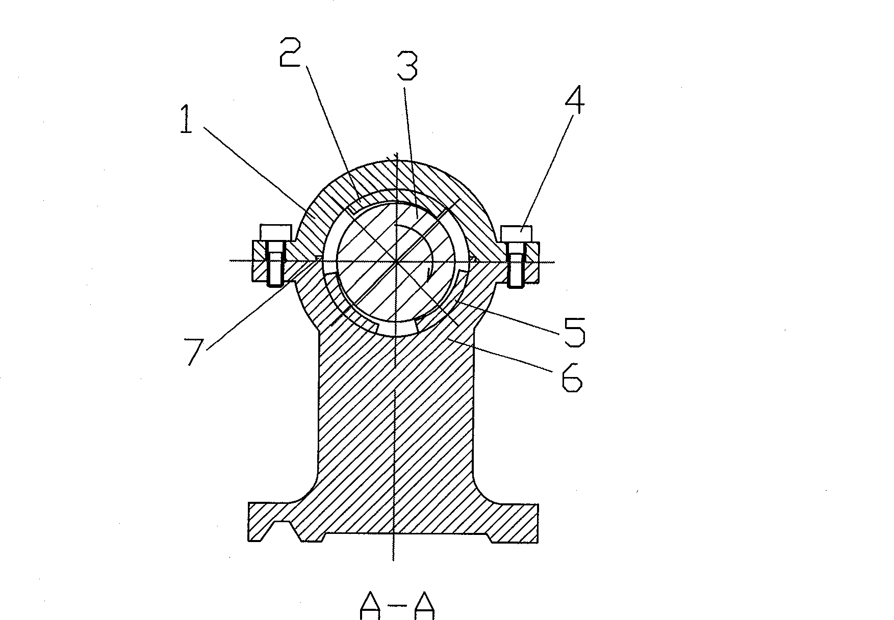
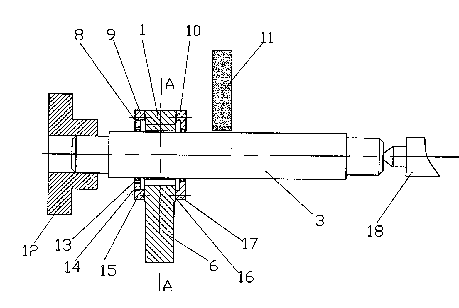
[0026] see figure 1 and figure 2 , the processed workpiece 3 is a high-precision spindle, one end of which is supported and clamped by the machine tool spindle chuck 12, and the other end is supported by the tailstock 18, and the surface of the processed workpiece 3 is ground by the emery wheel 11. Install the hydrodynamic center frame on the ground part of the processed workpiece 3, the machine tool hydrodynamic center frame includes an upper gland 1 and a center support 6 fixed by screws 4, and the upper gland 1 and the center A positioning notch 7 is provided between the supports 6 to ensure the positional accuracy after the two are assembled; The annular surface cooperates with the concave semicircular surface of the central support 6 to form a shaft machining hole; the upper bearing bush 2 is fixedly installed on the inner annular surface of the upper gland 1, and the concave semicircular surface of the central support 6 is evenly installed with Two lower bearing bushe...

Embodiment 2

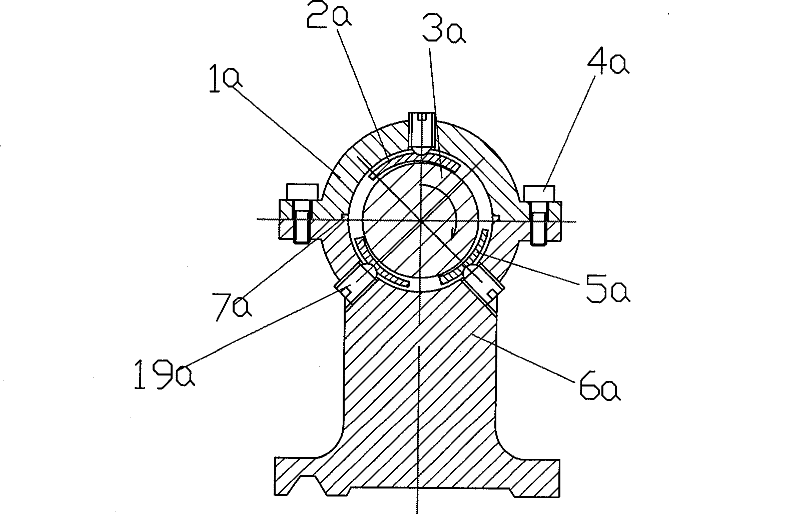
[0029] see image 3 and Figure 4 , the ball head adjustment screw 19a is installed radially on the upper gland 1a corresponding to the upper bearing bush 2a, and the ball head adjustment screw 19a is also installed on the center support 6a corresponding to the two lower bearing bushes 5a. The ball head is in the shape of a spherical segment; the backs of the upper bearing bush 2a and the two lower bearing bushes 5a corresponding to the ball head adjusting screw 19a are respectively provided with positioning circular sockets, and the positioning ball sockets on the backs of the upper bearing bush and the two lower bearing bushes are spherical pits; and The ball head adjusting screw 19a abuts on the positioning ball sockets on the back of the upper bearing bush 2a and the lower bearing bush 5a, and other structures are the same as in the first embodiment.

[0030] The upper bearing bush 2a and the lower bearing bush 5a can respectively swing around the ball head adjusting scre...

Embodiment 3

[0032] see Figure 5 and Figure 6 , the workpiece 3b to be processed is a large roll with a relatively large length and diameter, and the bending deformation caused by its own weight is the main factor affecting the machining accuracy. , to reduce the bending deformation caused by the workpiece's own weight. The ball head adjustment screw 19b is installed on the center support 6b, and the ball head of the ball head adjustment screw is in the shape of a spherical segment; the back of the bearing bush 5b corresponding to the ball head adjustment screw 19b is provided with a positioning ball socket, and the positioning ball socket on the back of the bearing pad is spherical pit; and the ball head adjustment screw 19b is supported on the positioning ball socket on the back of the bearing bush 5b, and other structures are the same as in Embodiment 1.

[0033] The bearing bush 5b can swing around the ball head adjustment screw 19b on its back to automatically adjust the gap. When...


PUM


Abstract

The invention relates to a liquid dynamic-pressing central frame of a machine tool, which solves the problems that the rigid central frame bearing of the machine tool has poor capability of absorbing the vibration of the workpiece, abrades the surface of the processed workpiece and has low bearing precision. The liquid dynamic-pressing central frame comprises an upper pressing cover and a central supporter which are correspondingly matched and fixed by screws. The liquid dynamic-pressing central frame is characterized in that the internal ring surface of the upper pressing cover is provided with an upper bearing; the lower concave semi-round surface of the central supporter is provided with more than one lower bearings; the working surface of the upper bearing and the lower bearing is Archimedean curved surface or eccentric arc surface; two side surfaces of the upper pressing cover in the axial direction are respectively provided with an upper-half end cover; two side surfaces of the lower-concave semi-round surface of the central supporter in the axial direction are respectively provided with a lower-semi end cover; the lower-half end cover at one side is provided with an oil inlet and the upper-half end cover is provided with an oil outlet. The liquid dynamic-pressing central frame is not rigidly contacted with the workpiece directly, generates no abrasion on the surface of the workpiece, can absorb and restrict the vibration of the supported bearing and has high bearing precision.

Description

technical field [0001] The invention relates to a machine tool accessory, specifically a machine tool center frame. Background technique [0002] When turning or grinding slender shaft parts, in order to reduce the bending deformation of the processed parts under the action of gravity or cutting force, a steady rest or a tool rest is often used on the machine tool to support the processed parts. The support of the existing center frame or tool rest to the processed parts is a rigid support. The center frame or the tool rest directly contacts the workpiece at the support point, such as the commonly used three-point contact center frame with rollers. , the rollers of the center frame are directly against the surface of the supported parts. Due to the rigid contact support of the existing steady rest or tool rest, there are the following deficiencies: the ability to absorb the vibration of the workpiece is poor, and even the additional vibration of the workpiece is generated, ...

Claims


Application Information

Patent Timeline
Patent Type & Authority Applications(China)
IPC IPC(8): B23Q1/76B23B25/00B24B5/35B24B5/04B24B41/06
Inventor 黄斌
Owner HEFEI UNIV OF TECH
Why Eureka
Try Eureka