
Method for testing wall parameter

A technology of parameter testing and walls, applied in the direction of measuring devices, radio wave measurement systems, radio wave reflection/re-radiation, etc., can solve the problems that cannot meet the needs of practical radar applications, stay in the theoretical research stage, etc., and achieve the calculation process Easy to meet the compensation and correction, the effect of simple test process

Inactive Publication Date: 2009-05-27
UNIV OF ELECTRONICS SCI & TECH OF CHINA
View PDF0 Cites 14 Cited by
  • Summary
  • Abstract
  • Description
  • Claims
  • Application Information

AI Technical Summary

Problems solved by technology

However, to compensate the influence of the wall, the premise is to obtain accurate wall parameters. The existing wall parameter estimation methods only stay in the theoretical research stage and cannot meet the needs of practical radar applications.

Method used


Image

  • Method for testing wall parameter
  • Method for testing wall parameter
  • Method for testing wall parameter

Examples


Embodiment 1

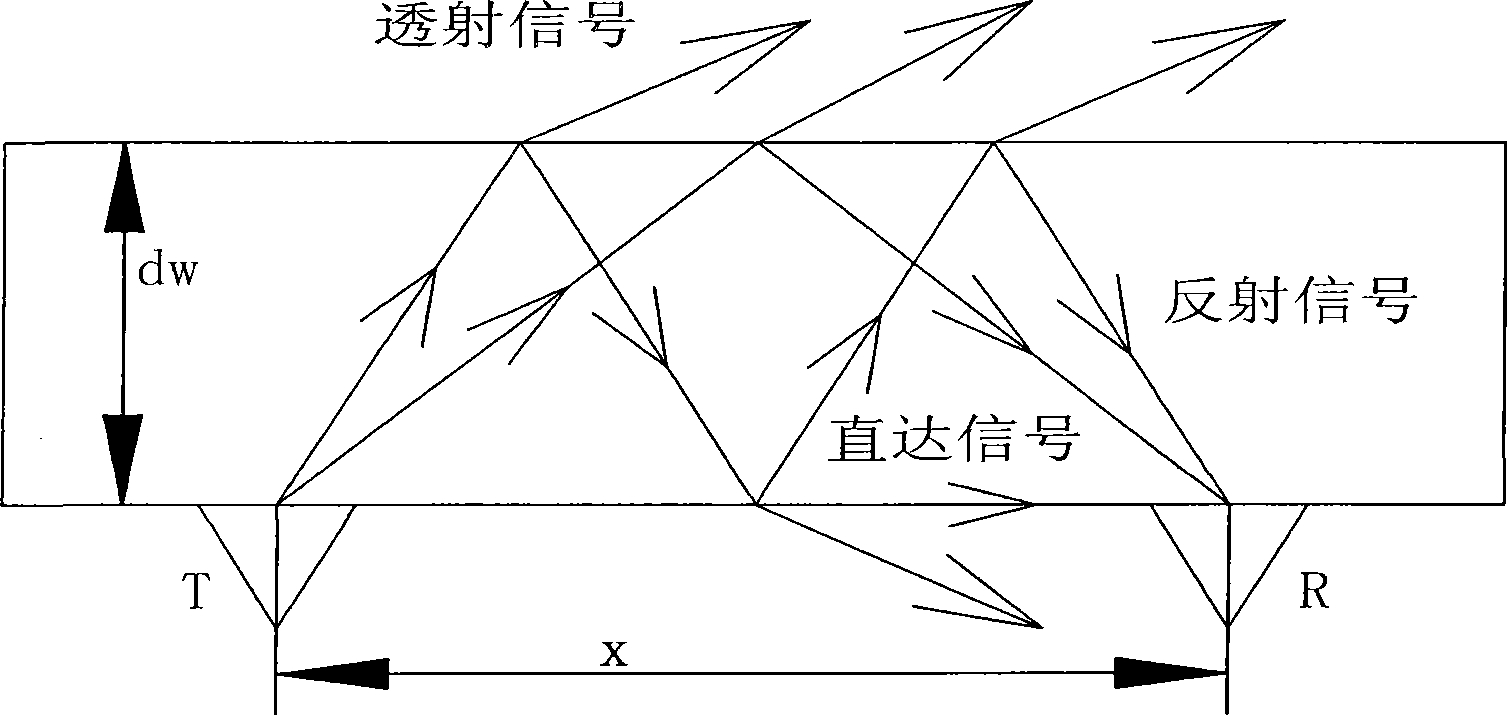
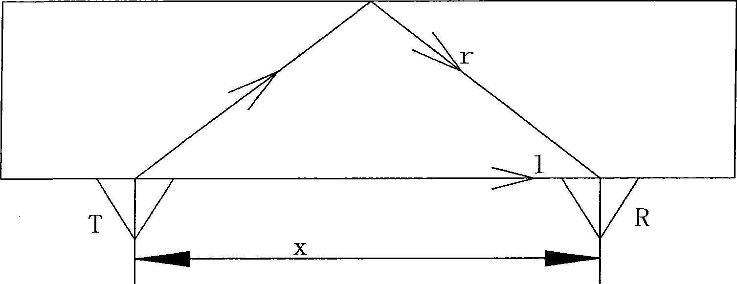
[0041] Such as figure 2 As shown, let the thickness of the wall be dw, and the dielectric constant of the wall be ε r , the transmitting antenna sticks to the wall to emit electromagnetic waves;

[0042] The receiving antenna R and the transmitting antenna T are attached to the wall on the same side, and the electromagnetic waves transmitted through the wall are collected at a distance of x meters, including the direct signal f l (t) and the wall once reflected signal f r (t);

[0043] From the echo signal, determine the direct signal f l The position l of (t) and the first reflection signal f of the wall r The position r of (t) has:

[0044] l = ϵ r × x

[0045] r = 2 ϵ r × dw 2 + ( ...

Embodiment 2

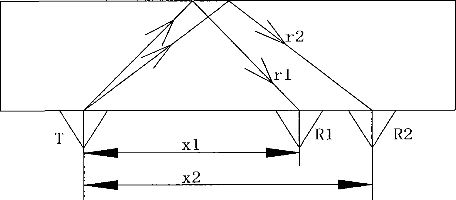
[0051] Such as image 3 As shown, when the distance between the receiving antenna R1 and the transmitting antenna T is x 1 When , determine the position r of the reflected signal from the wall from the echo signal 1 ; When the distance between the receiving antenna R2 and the transmitting antenna T is x 2 When , determine the position r of the reflected signal from the wall once 2 , then there are:

[0052] ( r 1 2 ) 2 = ϵ r × ( dw 2 + ( x 1 2 ) 2 )

[0053] ( ...


PUM


Abstract

The invention relates to wall-passing radar technology, in particular to wall-passing target positioning and imaging technology. The invention discloses a method for measuring wall parameters based on the position information of barrier reflected wave, which is used for compensating and regulating positioning, imaging and the like of hidden target. The test method for measuring wall parameters of the invention comprises the following steps: a. an emitting antenna is attached to the wall surface to emit electromagnetic waves; b. a receiving antenna is attached to the wall surface of the same side to receive the electromagnetic waves transmitted through the wall; c. the wall parameters are calculated based on the position information of the receiving signal. The technology has the beneficial effects that, the test procedure is simple, the operation process is easy to realize, and accurate wall electromagnetic parameters can be obtained on the condition that the other surface of the wall is inaccessible, thereby meeting the compensation and regulation of actual detecting positioning and imaging.

Description

technical field [0001] The invention relates to the wall-penetrating radar technology, in particular to the wall-penetrating target positioning and imaging technology. Background technique [0002] Through-the-Wall Surveillance (TWS) and Through-the-Wall Radar Imaging (TWRI) transmit electromagnetic wave signals of a certain frequency to penetrate barriers such as walls and buildings, relying on the concealment behind the receiving barrier The reflected wave information of the target realizes its detection, positioning, tracking and imaging. For example, in the fight against terrorism, the detection, positioning, tracking and status analysis of terrorists and hostages in buildings; the search and rescue of people in disaster ruins, etc. [0003] Due to the existence of barriers such as walls, large errors are brought about in positioning, tracking, and imaging, so the influence of walls needs to be compensated. To compensate the influence of the wall, the premise is to obt...

Claims


Application Information

Patent Timeline
Patent Type & Authority Applications(China)
IPC IPC(8): G01S7/02G01S7/40G01S13/02G01S13/89
Inventor 孔令讲崔国龙杨晓波杨建宇
Owner UNIV OF ELECTRONICS SCI & TECH OF CHINA
Learn More