Thermal mass gas flow sensor and method of forming same

A gas flow, sensor technology, applied in the field of flow sensors, can solve problems such as damage

Inactive Publication Date: 2009-05-27
HONEYWELL INT INC
View PDF5 Cites 26 Cited by
  • Summary
  • Abstract
  • Description
  • Claims
  • Application Information

AI Technical Summary

Problems solved by technology

[0004] Unfortunately, thermal mass gas flow meters, especially thermal mass air flow sensors, are susceptible to damage from repeated or prolonged exposure to liquids due to liquid condensation or liquid caused by immersion

Method used


Image

  • Thermal mass gas flow sensor and method of forming same
  • Thermal mass gas flow sensor and method of forming same
  • Thermal mass gas flow sensor and method of forming same

Examples


Embodiment Construction

[0030] The specific values ​​and configurations discussed in these non-limiting examples can vary and are used merely to illustrate at least one embodiment of the invention and are not intended to limit the scope of the invention.

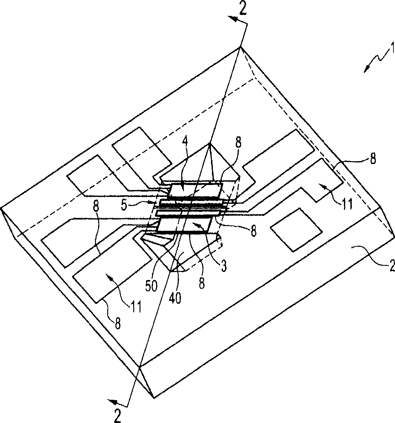
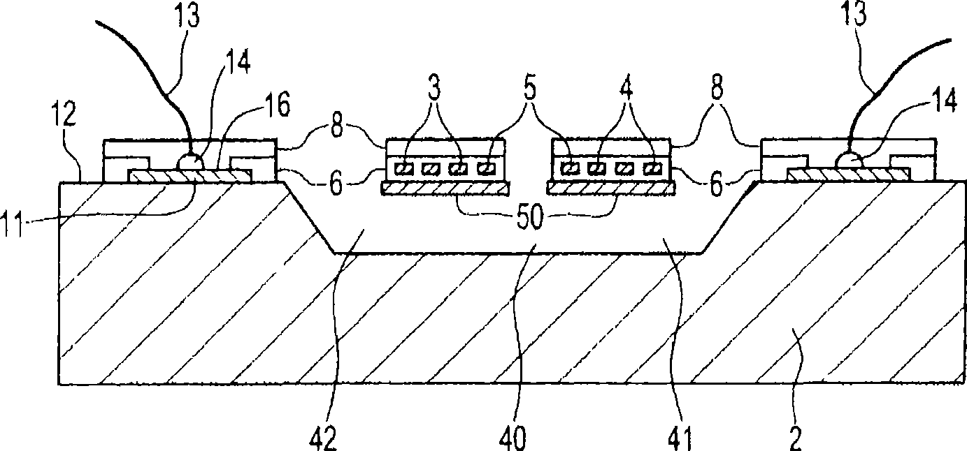
[0031] See attached picture, figure 1 shows a perspective view from above a thermal mass gas flow sensor according to one embodiment and figure 2 shows the case where the leads are bonded to the sensor along the figure 1 A cross-sectional view taken along line A-A in . As a general overview, a thermal mass gas flow sensor 1 has a substrate 2 and a heater 5 disposed on the substrate 2 between a pair of thermal sensing elements 3, 4 which are also installed on the substrate. A protective layer 8 is provided on the heater 5 and the thermal sensing elements 3 , 4 . This protective layer 8 is made of a high temperature resistant insulating or dielectric layer, preferably an organic layer, such as a polymer based layer. The protective layer minimiz...


PUM


Abstract

A thermal gas flow sensor and method of forming such a sensor. The sensor has a substrate and a heater disposed on the substrate. At least one pair of thermal sensing elements is disposed on the substrate either side of the heater. A protective layer is disposed on at least the heater and / or the thermal sensing elements. The protective layer comprises a high temperature resistant polymer based layer which is preferably a fluoropolymer based layer. The protective layer can also cover interconnects and electrical connections also formed on the substrate so as to completely seal the sensor. A passivation layer, such as silicon nitride, can be disposed on the sensing and / or heating elements and optionally the interconnects and is arranged to interpose the protective layer and the substrate.

Description

technical field [0001] Embodiments of the present invention generally relate to flow sensors, and in particular, embodiments of the present invention generally relate to thermal mass gas flow sensors, such as thermal air flow sensors, and methods of making such thermal gas flow sensors. Furthermore, embodiments of the present invention relate to thermal gas flow sensors in the form of microelectromechanical systems (MEMS) devices. Background technique [0002] Thermal mass gas flow sensors in the form of MEMS devices are configured to measure a property of a gas, such as air, in contact with the sensor and to provide an output signal indicative of the gas flow rate. Thermal mass gas flow sensors are configured to heat a gas and measure the resulting thermal properties of the gas in order to determine the flow rate. Such thermal flow sensors typically include a microsensor die that includes a substrate and one or more elements disposed on the substrate to heat a gas and sens...

Claims


Application Information

Patent Timeline
Patent Type & Authority Applications(China)
IPC IPC(8): G01F1/692
CPCG01F1/6845G01F1/692
Inventor R·W·格曼A·M·德米特里夫C·M·布伦霍夫
Owner HONEYWELL INT INC
Why Eureka
Try Eureka