Combusting system, remodeling method for combusting system, and fuel injection method for combusting system

一种燃烧装置、燃料喷射的技术,应用在燃烧方法、燃烧器安全装置、燃气轮机装置等方向,能够解决着火失败等问题,达到提高可靠性、提高环境性能的效果

Active Publication Date: 2009-06-03
MITSUBISHI POWER LTD
View PDF1 Cites 12 Cited by
  • Summary
  • Abstract
  • Description
  • Claims
  • Application Information

AI Technical Summary

Problems solved by technology

Therefore, the fuel supply timing becomes the same for all combustors of the gas turbine combustor, and even if the high-temperature combustor flows from the combustor ignited by the spark of the ignition device to the adjacent combustor, due to the non-adjacent combustor The ignition burner does not supply the required amount of fuel for flame propagation and ignition, which may cause ignition failure

Method used


Image

  • Combusting system, remodeling method for combusting system, and fuel injection method for combusting system
  • Combusting system, remodeling method for combusting system, and fuel injection method for combusting system
  • Combusting system, remodeling method for combusting system, and fuel injection method for combusting system

Examples


Embodiment 1

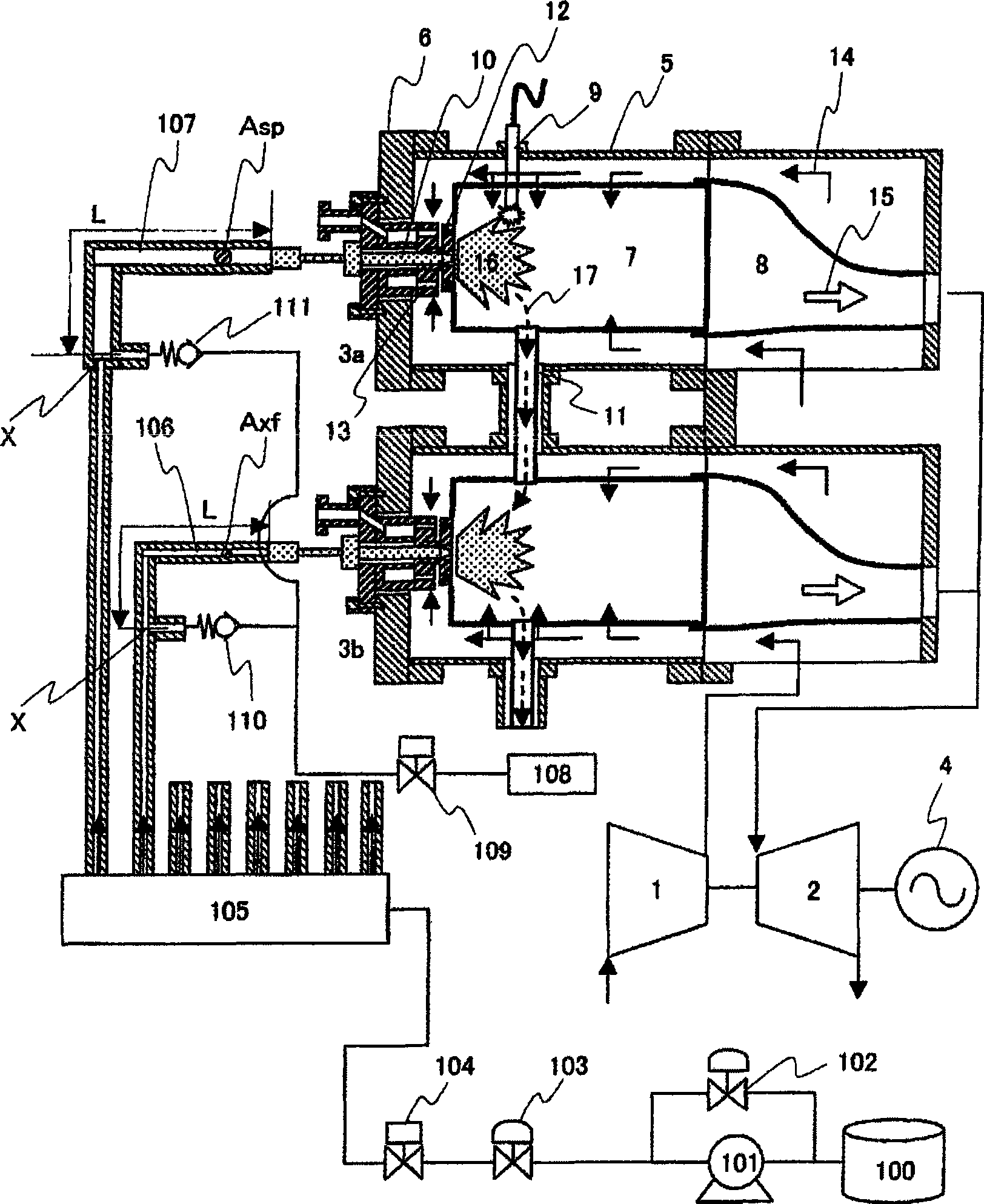
[0022] Below, refer to Figure 1 to Figure 4 with Figure 8 Example 1 will be described. This embodiment is an example where the combustion device is applied to a gas turbine.

[0023] figure 1 It is a schematic configuration diagram schematically showing the overall configuration of a gas turbine plant including the gas turbine combustor of the first embodiment. Such as figure 1 As shown, the gas turbine plant mainly includes: a compressor 1 that compresses air to generate high-pressure combustion air; a plurality of burners 3a that generate combustion gas 15 by mixing combustion air 14 introduced from the compressor 1 with fuel; 3b; and the turbine 2 that introduces the combustion gas 15 generated by the burners 3a, 3b. In addition, in figure 1 In the brief structural diagram, only two are represented in the 10 burners described later. Also, the shafts of the compressor 1 and the turbine 2 are connected.

[0024] The combustors 3a, 3b seal the following parts with th...

Embodiment 2

[0053] Below, refer to Figure 5 Example 2 will be described.

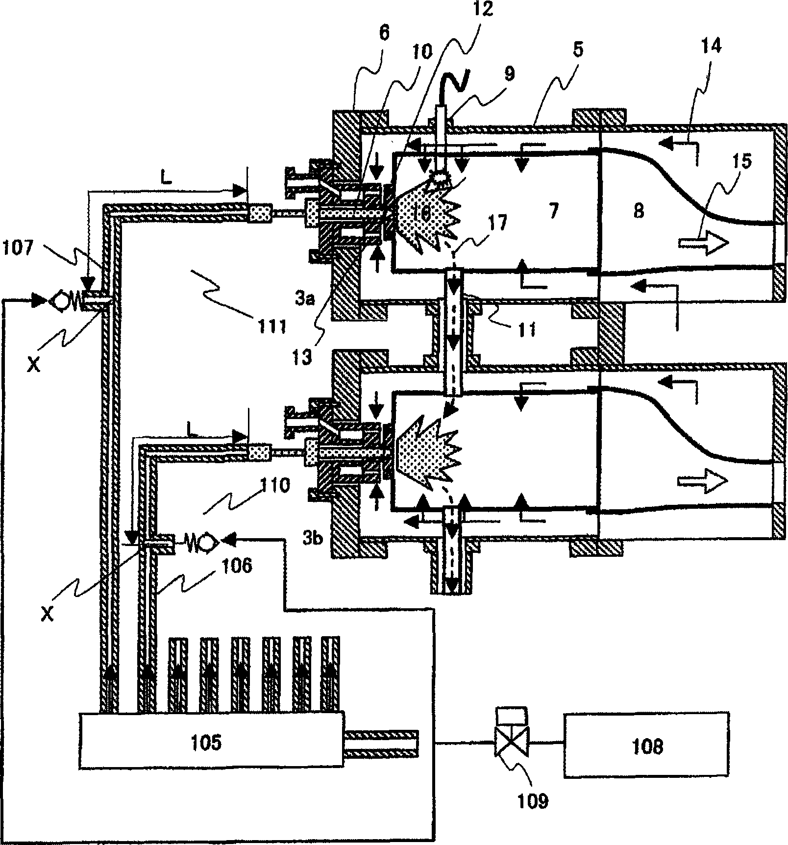
[0054] The basic components of the burner of the present embodiment have the same structure as that of the first embodiment. In the present embodiment, by forming the point X2 on the upstream side of the point X1, the fuel pipe 107 from the connection portion (point X2) of the fuel purification system of the burner 3a provided with the spark plug 9 to the inlet of the fuel nozzle The length L2 of is made longer than the length L1 of the fuel pipe 106 from the connection portion (X1 point) of the fuel purification system of the burner 3b without a spark plug to the fuel nozzle inlet.

[0055] According to the embodiment of the present invention constituted in this way, the volume of the fuel pipe 107 of the burner 3a having an ignition device can be made larger than the volume of the fuel pipe 106 of the burner 3b without an ignition device. 1 to the same effect.

[0056] In addition, in Embodiment 1, since the ...

Embodiment 3

[0059] Below, refer to Image 6 Embodiment 3 of the present invention will be described.

[0060] The burner of this embodiment is the same as that of Embodiment 2, and the cross-sectional areas of the fuel pipes 106, 107 of all the burners 3a, 3b are the same. The present embodiment is different in that the connection position for connecting the fuel purification system to the fuel piping is also the same. Let the piping distance from the connecting portion of the fuel purification system and the fuel piping to the fuel nozzle inlet be L3. Furthermore, in this embodiment, the three-way valve 113 is provided only on the upstream side of the fuel pipe 107 of the burner 3a provided with the spark plug 9 at a distance L4 (L3


PUM


Abstract

The invention relates to a combusting system, remodeling method for combusting system, and fuel injection method for combusting system. The present invention improves the reliability of a combusting system including multiple combustors and improves an environmental performance thereof. The invention includes a device that delays the start time of fuel injection from a fuel nozzle of a combustor including a ignitor from the start time of fuel injection from a fuel nozzle of the combustor not including the ignitor. Thus the combusting system including multiple combustors can improve the reliability of a combusting system and the environmental performance thereof.

Description

technical field [0001] The invention relates to a combustion device, a modification method of the combustion device and a fuel injection method of the combustion device. Background technique [0002] Patent Document 1 (JP-A-10-121986) discloses a gas turbine having a plurality of combustors. Generally, a gas turbine having a plurality of combustors is arranged in an annular shape along the periphery of the combustor gas turbine, and all adjacent combustors are connected between the combustors by flame propagation pipes. These flame propagation tubes cause combustion gases to flow inside the flame propagation tubes due to the pressure difference between the connected burners. An ignition device for generating an electric spark is provided in one or two burners of the plurality of burners. [0003] The start-up of the gas turbine uses external energy to increase the number of revolutions of the compressor and introduce air into the combustor. Thereafter, as the ignition com...

Claims


Application Information

Patent Timeline
Patent Type & Authority Applications(China)
IPC IPC(8): F23R3/28
CPCF02C3/14F02C7/264F23N2025/26F05D2260/85F23K5/06F05B2260/85F02C7/228F23D2209/30F23N2037/02F23N5/203F23R3/48F23N2027/04F23N2027/02F23N1/002F23N2225/26F23N2227/04F23N2227/02F23N2237/02
Inventor 平田义隆吉田正平关口达也井上洋
Owner MITSUBISHI POWER LTD
Why Eureka
Try Eureka