Fresh air unit with an air supplying and heat recovering device

A technology of fresh air processing unit and heat recovery device, which is applied in the energy recovery system of ventilation and heating, household heating, heating methods, etc. It can solve the problems of high energy consumption, cold and heat offset, etc., and improve the coefficient of performance and cost. Low cost and reduced energy consumption

Inactive Publication Date: 2009-06-03
HARBIN INST OF TECH
View PDF0 Cites 0 Cited by
  • Summary
  • Abstract
  • Description
  • Claims
  • Application Information

AI Technical Summary

Problems solved by technology

[0003] The purpose of the present invention is to provide a fresh air treatment unit with a supply air heat recovery device to solve the problem of high energy consumption due to the offset of cold and heat in the process of air treatment in the reheating air supply system

Method used


Image

  • Fresh air unit with an air supplying and heat recovering device
  • Fresh air unit with an air supplying and heat recovering device

Examples


specific Embodiment approach 1

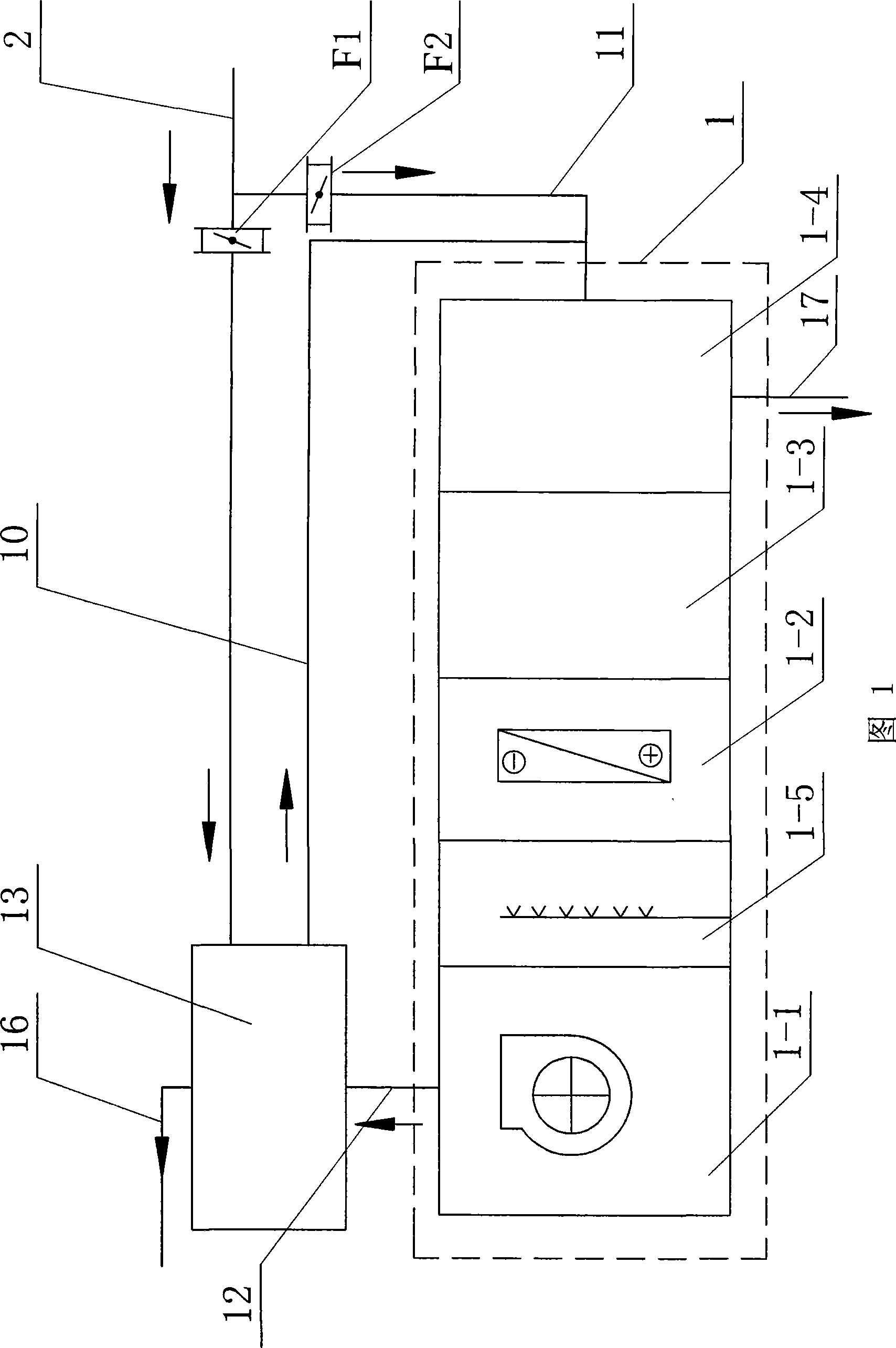
[0007] Specific Embodiment 1: As shown in Figure 1, the fresh air treatment unit with air supply heat recovery device described in this embodiment includes a fresh air treatment unit 1, a fresh air pipeline 2, a first air volume regulating valve F1, a second air volume Regulating valve F2, first connecting pipeline 10, second connecting pipeline 11 and third connecting pipeline 12, the fresh air processing unit 1 is composed of air supply section 1-1, humidifying section 1-5, table The cold section 1-2, the mixing section 1-3 and the exhaust air heat recovery device 1-4 are composed; the fresh air processing unit also includes a supply air heat recovery device 13; The two ends of the second connecting pipeline 11 communicate with the fresh air pipeline 2 and the exhaust air heat recovery device 1-4, and the two ends of the first connecting pipeline 10 communicate with the air supply heat recovery device 13 It communicates with the second connecting pipeline 11, the first air v...

specific Embodiment approach 2

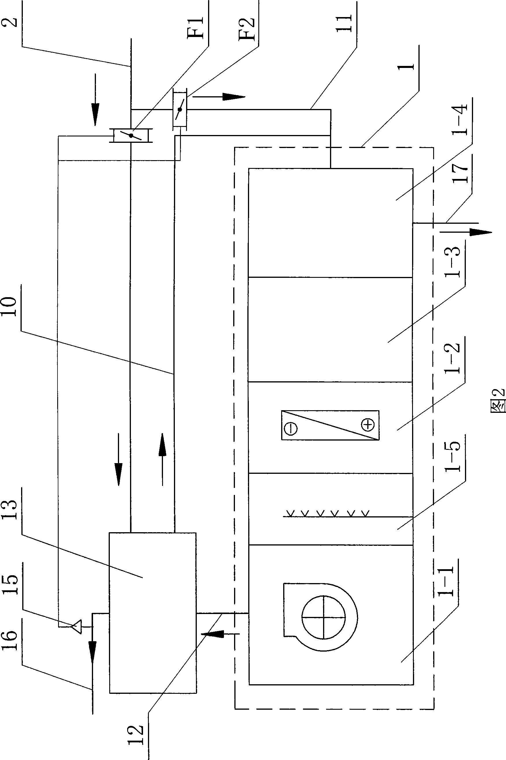
[0008] Embodiment 2: As shown in FIG. 1 , the second connecting pipeline ( 11 ) in this embodiment is a right-angle elbow. Such setting facilitates the connection with the air-conditioning processing unit 1 . Other components and connections are the same as those in the first embodiment.

[0009] The working principle of the present invention is (in conjunction with Fig. 2 description): a part of outdoor fresh air enters into the air supply heat recovery device 13 (for air supply heat recovery) through the fresh air pipeline 2, and then passes through the first connecting pipeline 10 and the second The connecting pipeline 11 enters the exhaust air heat recovery device 1-4 of the air conditioning processing unit 1 (for exhaust air heat recovery); another part of outdoor fresh air enters the exhaust air heat recovery of the air conditioning processing unit 1 through the second connecting pipeline 11 1-4 (exhaust air heat recovery), then enters the mixing section 1-3 of the air ...


PUM


Abstract

A fresh air unit with an air supplying and heat recovering device relates to a fresh air unit and solves problems of counteraction between cold energy and heat energy and high energy consumption, which exist in air treating process of a reheating type air supplying system. The fresh air unit also comprises the air supplying and heat recovering device; one end of a fresh air pipeline is communicated with the air supplying and heat recovering device; two ends of a second connecting pipeline are communicated with the fresh air pipeline and an air discharging and heat recovering device; two ends of a first connecting pipeline are communicated with the air supplying and heat recovering device and the second connecting pipeline; a first air amount regulating valve is arranged on the fresh air pipeline between the second connecting pipeline and the air supplying and heat recovering device; a second air amount regulating valve is arranged on the second connecting pipeline; and an air supplying section is communicated with the air supplying and heat recovering device by a third connecting pipeline. By taking advantage of the air supplying and heat recovering device, the invention effectively solves the problem of counteraction between cold energy and heat energy and reduces energy consumption of the system.

Description

technical field [0001] The invention relates to a fresh air processing unit. Background technique [0002] The fresh air processing unit is a common equipment in the air conditioning system and has been widely used in various central air conditioning systems. The air supply methods of the existing fresh air processing units are generally divided into two types: dew point air supply and reheat air supply. But both approaches have problems to varying degrees. The main problems of the dew point air supply system are: 1. The temperature and humidity are coupled with each other, and the adjustment performance is poor, so it is difficult to strictly control the temperature and humidity; 2. The temperature difference of the air supply is large, the air supply volume is small, and the room temperature is uniform. 3. The dew point temperature achieved by the air cooling treatment is low, resulting in a low coefficient of performance of the refrigeration system. The main problem of...

Claims


Application Information

Patent Timeline
Patent Type & Authority Applications(China)
IPC IPC(8): F24F3/06F24F3/14F24F12/00
Inventor 姜益强姚杨柴永金董建锴
Owner HARBIN INST OF TECH
Why Eureka
Try Eureka