Air-handling unit with air blast thermal recovery machine

A technology of air handling unit and heat recovery device, which is applied in the energy recovery system of ventilation and heating, using air flow as shielding, household heating, etc., can solve the problems of cold and heat offset, high energy consumption, etc., to solve the offset problem , Reduce system energy consumption, simple and reasonable structure

Inactive Publication Date: 2010-06-23
HARBIN INST OF TECH
View PDF2 Cites 0 Cited by
  • Summary
  • Abstract
  • Description
  • Claims
  • Application Information

AI Technical Summary

Problems solved by technology

[0003] The purpose of the present invention is to provide an air handling unit with an air supply heat recovery device to solve the problem of high energy consumption due to the offset of cold and heat in the air treatment process in the reheating air supply system

Method used


Image

  • Air-handling unit with air blast thermal recovery machine
  • Air-handling unit with air blast thermal recovery machine
  • Air-handling unit with air blast thermal recovery machine

Examples


specific Embodiment approach 1

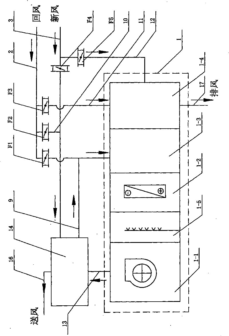
[0007] Specific implementation mode one: combine figure 1 Describe this embodiment. The air handling unit in this embodiment includes an air conditioning processing unit 1, a return air pipeline 2, a fresh air pipeline 3, a first air volume regulating valve F1, a second air volume regulating valve F2, and a third air volume regulating valve F3. , the fourth air volume regulating valve F4, the fifth air volume regulating valve F5, the first connecting pipeline 9, the second connecting pipeline 10, the third connecting pipeline 11, the fifth connecting pipeline 12 and the sixth connecting pipeline 13, The air conditioning treatment unit 1 is composed of an air supply section 1-1, a humidification section 1-5, a surface cooling section 1-2, a mixing section 1-3 and an exhaust heat recovery device 1-4 connected in series; the air The processing unit also includes an air supply heat recovery device 14; one end of the return air pipeline 2 communicates with the mixing section 1-3, o...

specific Embodiment approach 2

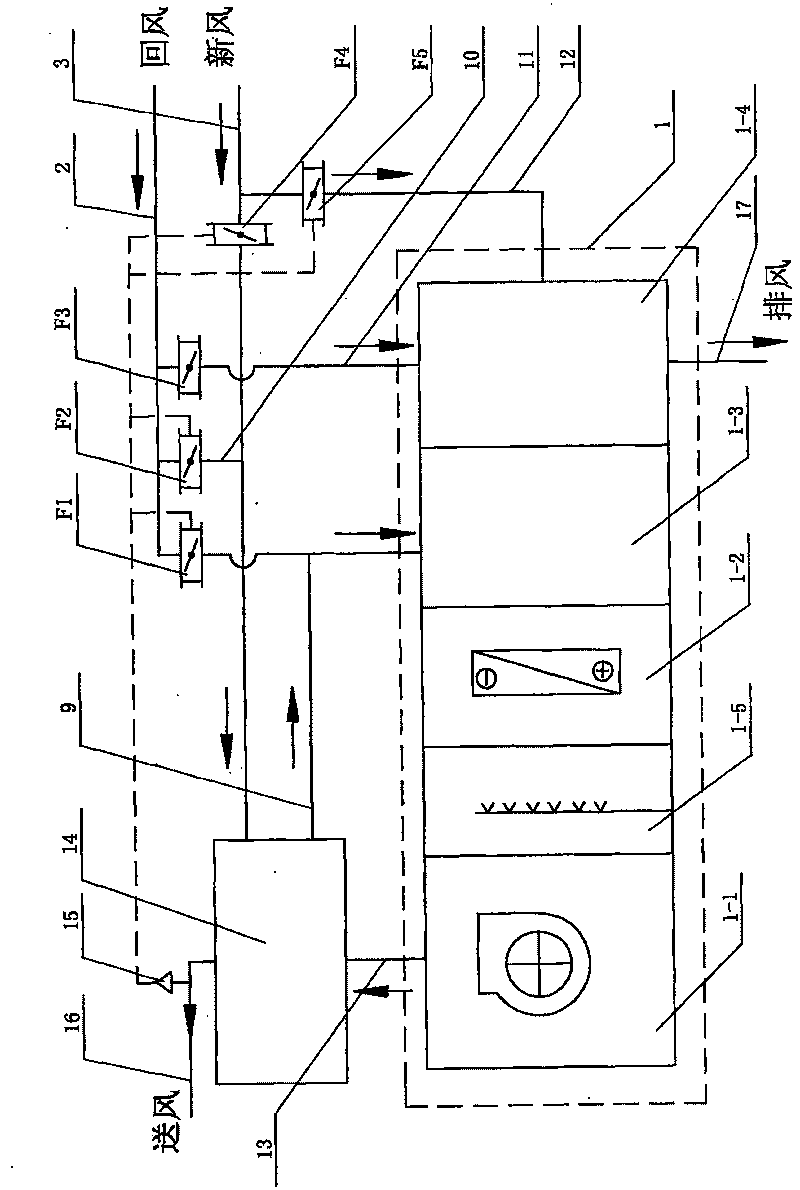
[0008] Specific implementation mode two: combination figure 1 To describe this embodiment, the return air pipeline 2 and the fifth connecting pipeline 12 in this embodiment are both right-angle elbows. Such setting facilitates the connection with the air-conditioning processing unit 1 .

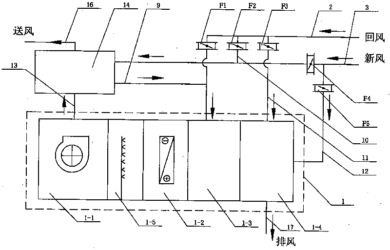
[0009] The working principle of the present invention is (in combination with figure 2 Explanation): If the fresh air volume is sufficient, the second air volume regulating valve F2 is closed, the first air volume regulating valve F1, the fourth air volume regulating valve F4 and the fifth air volume regulating valve F5 are opened, and a part of outdoor fresh air enters into the delivery system through the fresh air pipeline 3 In the air heat recovery device 14 (for air supply heat recovery), it enters the mixing section 1-3 of the air conditioning treatment unit 1 through the first connecting pipeline 9 and the return air pipeline 2; another part of outdoor fresh air passes through the fif...


PUM


Abstract

The invention provides an air treatment machine set with an air-supply heat recoverer, and relates to an air treatment machine set, and aims at the problems that a reheating-type air supply system has cold and heat counteracted and is high in energy consumption. A return air pipeline is communicated with a mixing section; a fresh air pipeline is communicated with the air-supply heat recoverer; two ends of a third connecting pipeline are communicated with the return air pipeline and an air exhaust heat recoverer; two ends of a fifth connecting pipeline are communicated with the fresh air pipeline and the air exhaust heat recoverer; two ends of a second connecting pipeline are communicated with the return air pipeline and the fresh air pipeline; two ends of a first connecting pipeline are communicated with the air-supply heat recoverer and the return air pipeline; a fourth air volume regulating valve is arranged on the fresh air pipeline between the second connecting pipeline and the fifth connecting pipeline; a first air volume regulating valve is arranged on the return air pipeline between the first connecting pipeline and the second connecting pipeline; a second air volume regulating valve, a third air volume regulating valve and a fifth air volume regulating valve are arranged on the second connecting pipeline, the third connecting pipeline and the fifth connecting pipeline;and an air supply section is communicated with the air-supply heat recoverer through a sixth connecting pipeline. The machine set has the advantages of effectively solving the problem of cold-heat counteraction and reducing system energy consumption through the air-supply heat recoverer.

Description

technical field [0001] The invention relates to an air handling unit. Background technique [0002] The air handling unit is a common equipment in the air conditioning system and has been widely used in the central air conditioning system. The existing air supply mode of the whole air system is generally divided into primary return air system and secondary return air system, and the primary return air system is further divided into dew point air supply and reheat air supply. There are certain problems. The main problems of the dew point air supply system are: 1. The temperature and humidity are coupled with each other, and the adjustment performance is poor, so it is difficult to strictly control the temperature and humidity; 2. The temperature difference of the air supply is large, the air supply volume is small, and the room temperature is uniform. 3. The dew point temperature achieved by the air cooling treatment is low, resulting in a low coefficient of performance of ...

Claims


Application Information

Patent Timeline
Patent Type & Authority Patents(China)
IPC IPC(8): F24F3/06F24F3/14F24F12/00
CPCY02P80/15
Inventor 姜益强姚杨柴永金牛福新
Owner HARBIN INST OF TECH
Why Eureka
Try Eureka