Heat exchanger performance testing device for air conditioning

A technology of heat exchangers and heaters, applied in measuring devices, testing of machines/structural components, instruments, etc., can solve problems such as high testing costs, inconvenient testing, and inability to adjust the capacity of the tested machine, and reduce testing costs , Ease of electrical control

Active Publication Date: 2010-06-09
HEFEI GENERAL ENVIRONMENT CONTROL TECH
View PDF0 Cites 0 Cited by
  • Summary
  • Abstract
  • Description
  • Claims
  • Application Information

AI Technical Summary

Problems solved by technology

For the performance test of this kind of machine, the following method is usually used in the past: if the evaporator is tested, according to the design of the tested machine or the estimated heat transfer, a compressor with a suitable capacity, a condenser and a throttle valve and Important pipelines and valves such as oil separators, gas-liquid separators, filters, etc., are combined into a typical refrigeration and air-conditioning system, which may cause a special set of components to be equipped for each tested machine and equipment, which will greatly increase the cost and complexity of testing
During the test, since the capacity of the compressor is fixed, the capacity of the tested machine cannot be adjusted, it depends entirely on the capacity of the compressor, the working condition adjustment range is very narrow, and the capacity is discontinuous, which is not convenient for product development In addition, electrical appliances and control systems cannot be integrated, which brings problems such as high test cost and complicated experimental process to the test unit.

Method used


Image

  • Heat exchanger performance testing device for air conditioning
  • Heat exchanger performance testing device for air conditioning
  • Heat exchanger performance testing device for air conditioning

Examples


Embodiment 1

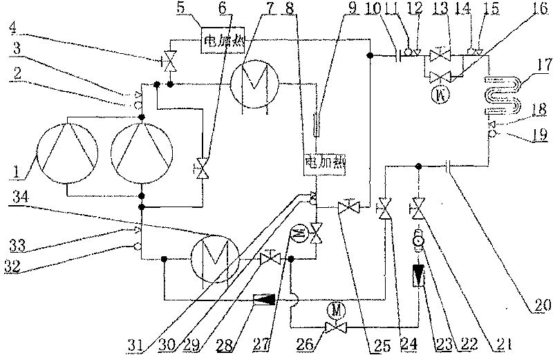
[0024] See figure 1 , The air conditioning heat exchanger performance test device includes two parallel-connected refrigeration compressors 1, condenser 7, evaporator 34 and heater;

[0025] The outlets of the two parallel refrigeration compressors 1 are connected to the inlet of the condenser 7 through a pipe, the outlet of the condenser 7 is connected to the inlet of the subcooler 9, and the outlet of the subcooler is connected to the heater B8 and the other of the heater B8. One end is connected to the inlet of the evaporator 34, and the outlet of the evaporator 34 is connected to the inlets of two parallel refrigeration compressors 1;

[0026] Two parallel refrigeration compressors 1 are connected in parallel with regulating valve A6;

[0027] The outlets of the two parallel refrigeration compressors 1 are equipped with discharge temperature measurement point 2 and discharge pressure measurement point 3, and the inlet is equipped with refrigeration compressor suction temperature ...


PUM


Abstract

The invention relates to a heat exchanger performance testing device for air conditioning. The device solves the problems of high cost of performance test and complex testing process of the prior heatexchanger for air conditioning. The device comprises two refrigeration compressors connected in parallel, the outlets of the two refrigeration compressors are communicated with a condenser, the condenser is communicated with a subcooler, the subcooler is connected with a heater, an evaporator is connected at the other end of the heater, and the evaporator is communicated with the inlets of the two refrigeration compressors connected in parallel; regulating valves are connected on the two refrigeration compressors connected in parallel in parallel; exhaust temperature measuring points and exhaust pressure measuring points are arranged at the outlets of the two refrigeration compressors connected in parallel, and suction temperature measuring points and suction pressure measuring points forthe refrigeration compressors are arranged at the inlets of the two refrigeration compressors connected in parallel; and temperature and pressure measuring points are also respectively arranged on other pipelines. The invention has the advantages that firstly, the wide-range stepless regulation for the capacity of the tested heat exchanger is realized, and the electric control is easy to realize;and secondly, the capacity of the tested heat exchanger can be adjusted within a small range.

Description

Technical field [0001] The invention relates to a performance test device for a heat exchanger for air conditioning. Background technique [0002] The heat exchanger for air conditioning (hereinafter referred to as the machine) is a part assembled in the factory. The refrigerant flows on one side of the tube and exchanges heat with the air (or water) flowing on the other side of the tube. When air (or water) passes through the component, the air (or water) and refrigerant exchange heat. Most of the machines are used in condensers and evaporators in air conditioners. For the performance test of this kind of machine, the following methods were usually used in the past: For example, to test the evaporator, according to the design of the machine under test or the estimated heat exchange amount, the compressor, condenser and throttle valve with suitable capacity are selected and Important pipelines and valves such as oil separators, gas-liquid separators, filters, etc., are equipped...

Claims


Application Information

Patent Timeline
Patent Type & Authority Patents(China)
IPC IPC(8): G01M19/00G01M99/00
Inventor 张秀平田旭东岳海兵周全许敬德郑传经
Owner HEFEI GENERAL ENVIRONMENT CONTROL TECH
Why Eureka
Try Eureka