Refrigeration device for trailer

A refrigeration device and trailer technology, which is applied to household refrigeration devices, applications, coolers, etc., can solve the problems of large space and no specific consideration of the configuration structure of the condenser and evaporator, and achieve efficient use of space, save space, and ensure heat The effect of the exchange area

Active Publication Date: 2009-06-03
DAIKIN IND LTD
View PDF1 Cites 4 Cited by
  • Summary
  • Abstract
  • Description
  • Claims
  • Application Information

AI Technical Summary

Problems solved by technology

[0003] However, in the refrigerating apparatus of the above-mentioned Patent Document 1, the arrangement structure of the condenser, the evaporator, etc. is not considered in detail, and the space required for installation is large.

Method used


Image

  • Refrigeration device for trailer
  • Refrigeration device for trailer
  • Refrigeration device for trailer

Examples


no. 1 approach

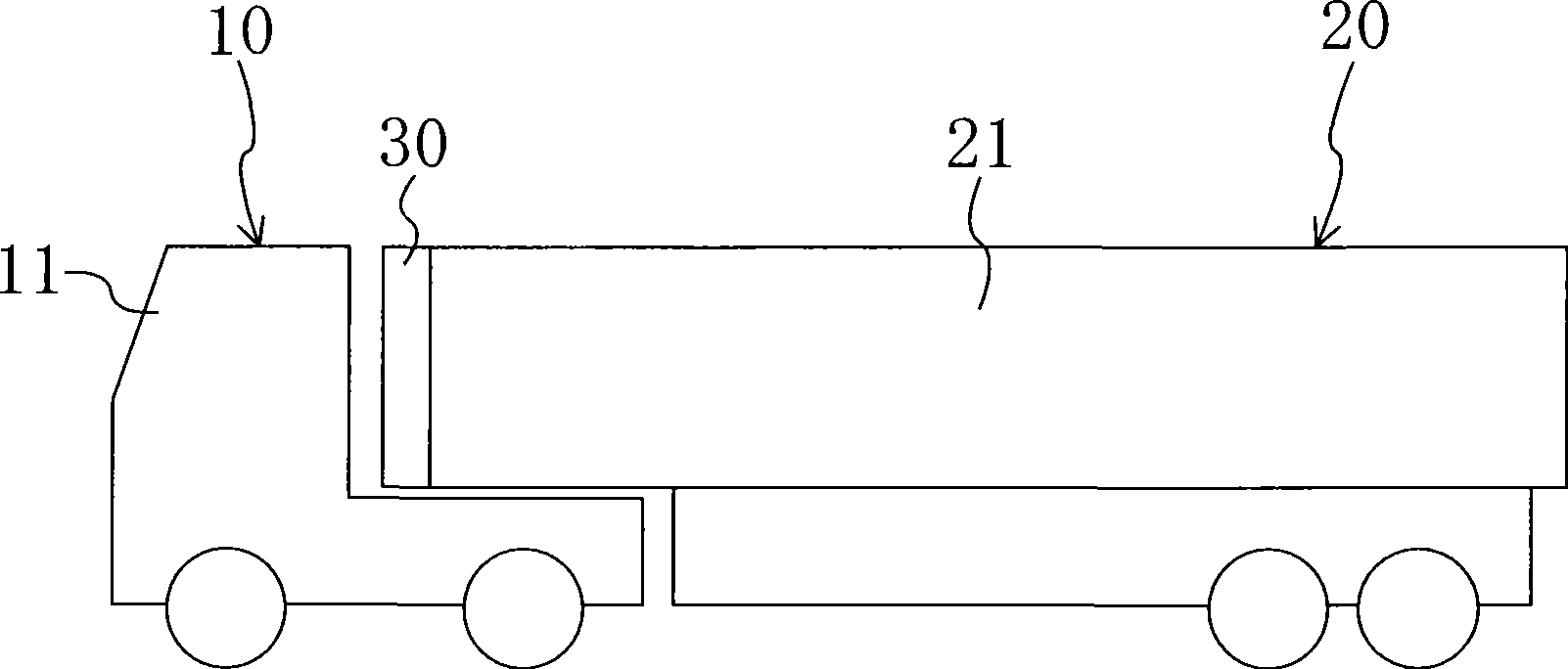
Such as figure 1 As shown, in the present embodiment, the trailer refrigerating device 30 is employed in a large refrigerated vehicle 10 that transports frozen foods, fresh foods, and the like by land.

[0038] In the refrigerated vehicle 10 , a trailer head 11 and a trailer 20 , which is a vehicle for driving and provided with a driving engine (not shown), are detachably connected. The refrigeration device 30 is installed in the trailer 20 to cool the inside of the trailer main body 21 .

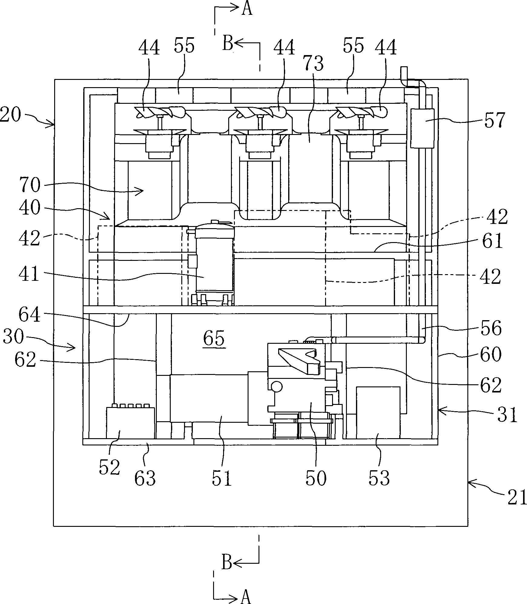
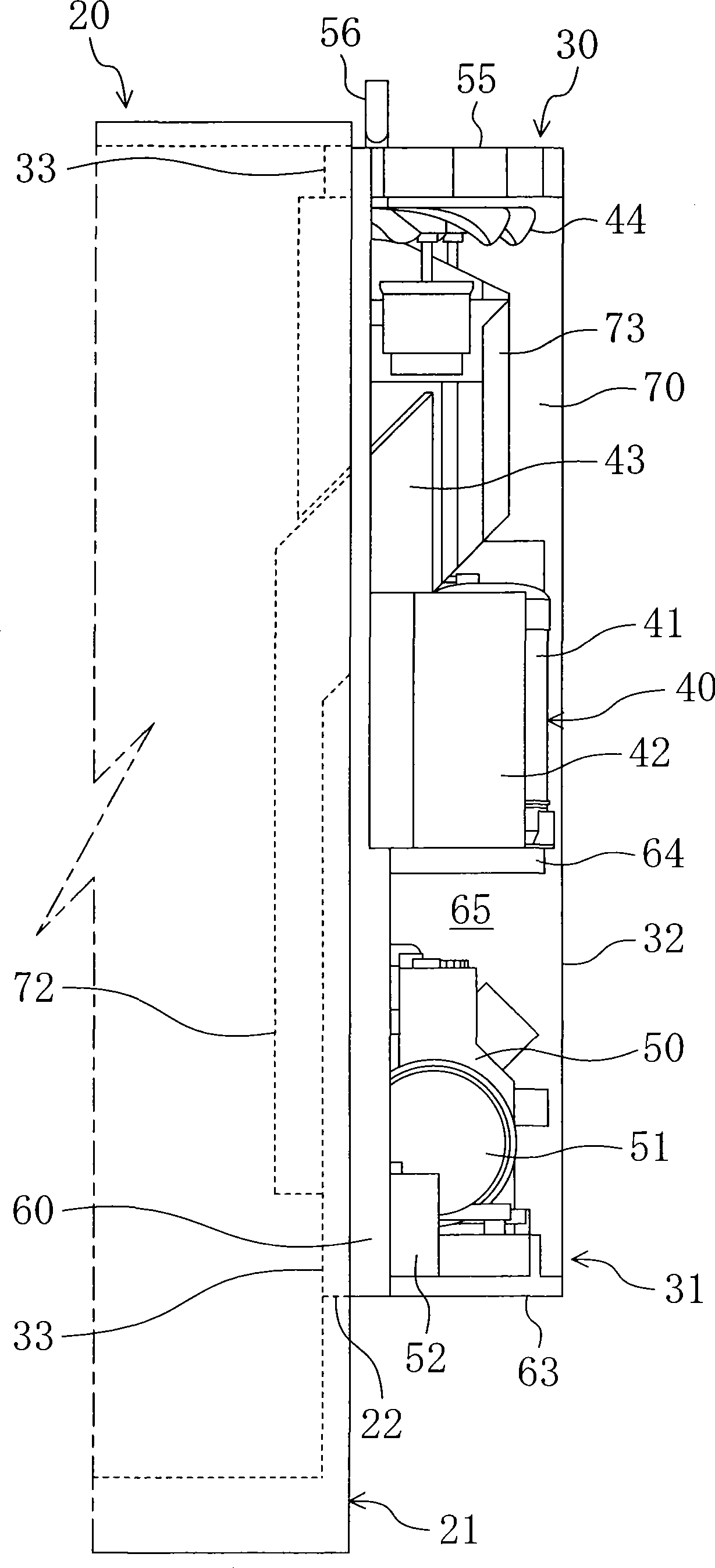
[0039] Such as Figure 2 to Figure 9 As shown, the refrigerating device 30 includes a refrigerating device main body 31 constituted by a frame structure as a reinforcing member, and the refrigerating device main body 31 includes a refrigerant circuit 40 and includes a power generating engine 50 and a generator 51 . The refrigerant circuit 40 includes a compressor 41, a condenser 42, an expansion mechanism (not shown), and an evaporator 43, and is configured to perform a vapor compression r...

no. 2 approach

Next, a second embodiment of the present invention will be described in detail with reference to the drawings.

[0072] Such as Figure 10 to Figure 17As shown, in this embodiment, the electrical equipment box 54 is arranged on the side of the condenser 42 instead of the method of arranging the electrical equipment box 54 behind the condenser 42 in the first embodiment.

[0073] Specifically, a low height portion 66 is formed on one side of the intermediate frame 64 of the refrigeration device main body 31 . The condenser 42 is arranged on the low height portion 66 , and the condenser 42 and the electrical equipment box 54 are arranged on the other side of the middle frame 64 . Therefore, maintenance can be easily performed from the front side of the refrigerator main body 31 facing the electrical equipment box 54 .

[0074] Furthermore, the compressor 41 is arranged on the back side of the condenser 42 of the low height portion 66 . In addition, although not shown in the dr...

no. 3 approach

[0076] Such as Figure 18 to Figure 25 As shown, in this embodiment, the evaporator 43 is arranged in an inclined state, instead of arranging the evaporator 43 in the vertical direction in the first embodiment.

[0077] Specifically, as Figure 24 As shown, the evaporator 43 is arranged in an inclined state with the upper part positioned behind the lower part, that is, in a state where the upper part protrudes toward the trailer body 21 . The angle of inclination is, for example, 20°.

[0078] In addition, the suction duct 72 is configured to open toward the evaporator 43 obliquely so that the air in the trailer body 21 is guided to the entire surface of the evaporator 43 .

[0079] In addition, a low height portion 66 is formed on one side of the intermediate frame 64 of the refrigeration device main body 31 . The compressor 41 is arranged on the low height portion 66 , and the electrical equipment box 54 is arranged above the compressor 41 . Therefore, maintenance can be...


PUM


Abstract

The present invention provides a refrigeration device body (31) at a trailer (20). A refrigerant circuit (40), an engine (50), and a generator (51) are received in the refrigeration device body (31). Further, a condensation side path (70) is formed in a portion from the front face to the upper face of the refrigeration device body (31). A condenser (42), an electrical equipment box, condenser fans (44), and a radiator (55) are sequentially and searially arranged in the condensation side path (70) from the upstream side to the downstream side. Also, an evaporation side path is formed in the refrigeration device body (31). The condenser fans (44) located in the condensation side path (70) and evaporator fans located in the evaporation side path are alternately arranged in the lateral direction of the refrigeration device body (31).

Description

technical field [0001] The invention relates to a refrigeration device for a trailer, in particular to the structure in the main body of the refrigeration device. Background technique [0002] Conventionally, a refrigeration device is known (for example, refer to Patent Document 1) that is installed in a refrigerated vehicle for ground transportation of frozen foods and the like, and cools the interior of the refrigerator of the refrigerated vehicle. The refrigerating device includes an auxiliary engine different from the driving engine of the refrigerated vehicle and an electric compressor driven by the auxiliary engine, and is arranged on a loading platform. Patent Document 1: Japanese Laid-Open Patent Publication No. Hei 5-38933. [0003] However, in the refrigerating apparatus of the above-mentioned Patent Document 1, the arrangement structure of the condenser, the evaporator, etc. is not specifically considered, and the space required for installation is large. this ...

Claims


Application Information

Patent Timeline
Patent Type & Authority Applications(China)
IPC IPC(8): F25D11/00F25D19/00F25D29/00B60P3/20B62D53/06
CPCF25D11/003F25D19/003B60H1/3226B60P3/20B60H1/3232
Inventor 北野茂一西浜幸夫工藤启介
Owner DAIKIN IND LTD
Why Eureka
Try Eureka