Dishware cleaner

A tableware washing machine and cleaning tank technology, applied in the direction of tableware washing machine/rinsing machine, tableware washing machine/rinsing and rinsing machine parts, automatic detection under the control of tableware washing machine/rinsing machine, etc., capable of solving ultrasonic vibrator failures , The ultrasonic vibrator stops working, affects the work of the ultrasonic vibrator, etc.

Inactive Publication Date: 2009-06-10
PANASONIC CORP
View PDF2 Cites 3 Cited by
  • Summary
  • Abstract
  • Description
  • Claims
  • Application Information

AI Technical Summary

Problems solved by technology

Therefore, there is a problem as follows: the solidified foreign matter on the vibrating surface affects the operation of the ultrasonic vibrator 14, and the amount of atomization is significantly reduced, or in serious cases, the ultrasonic vibrator itself fails, and the ultrasonic vibrator stops working.

Method used


Image

  • Dishware cleaner
  • Dishware cleaner
  • Dishware cleaner

Examples


Embodiment Construction

[0018] Hereinafter, one embodiment of the present invention will be described with reference to the drawings. In addition, the same code|symbol is attached|subjected to the same structure as a conventional example, and the description is abbreviate|omitted. In addition, this invention is not limited to this embodiment.

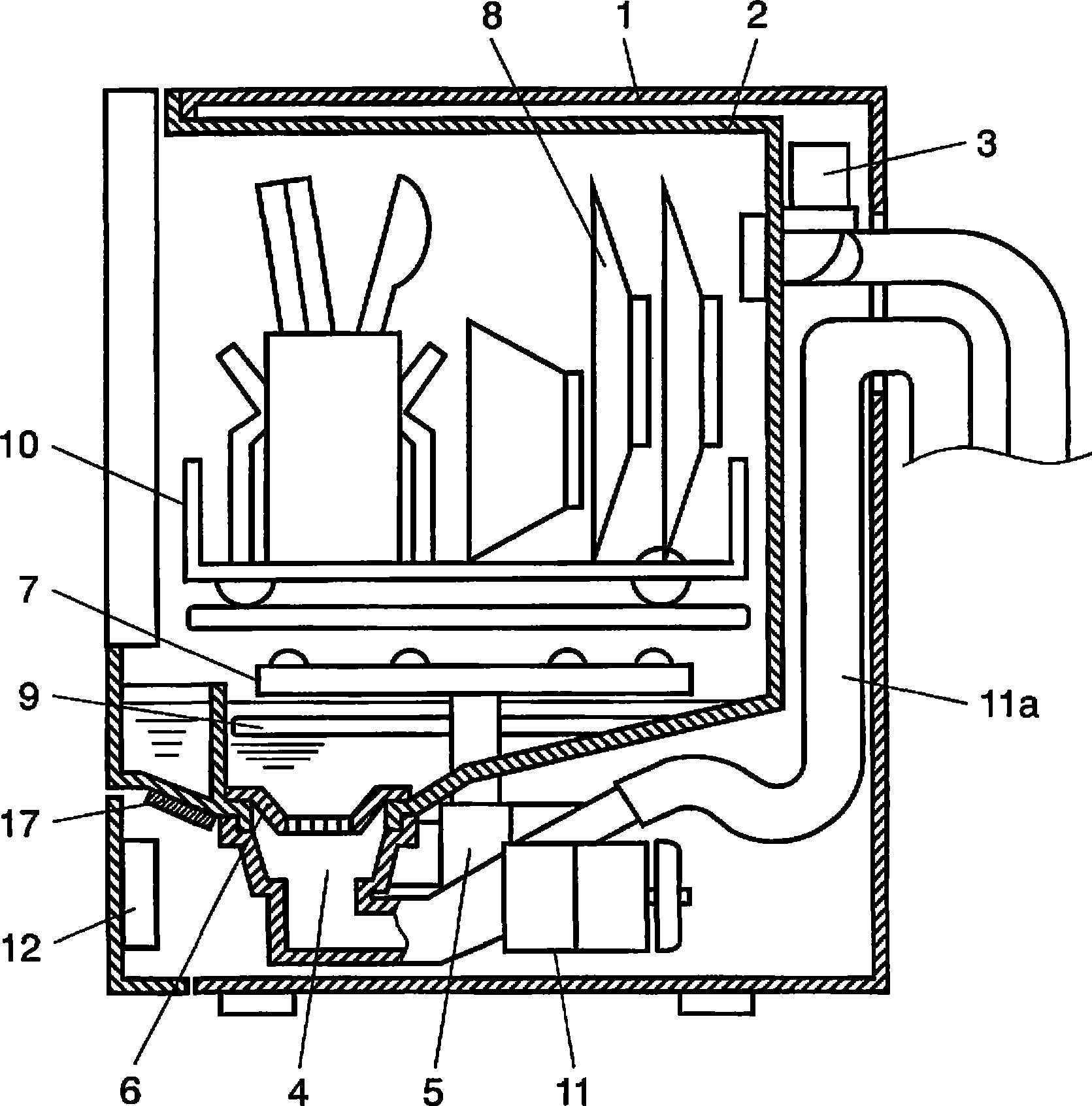
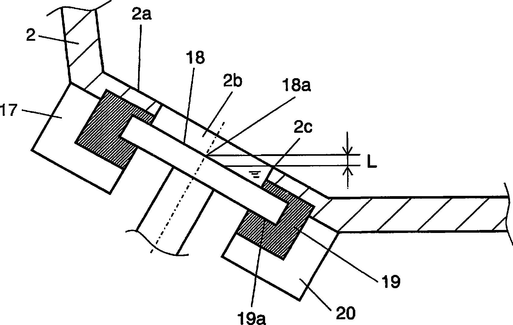
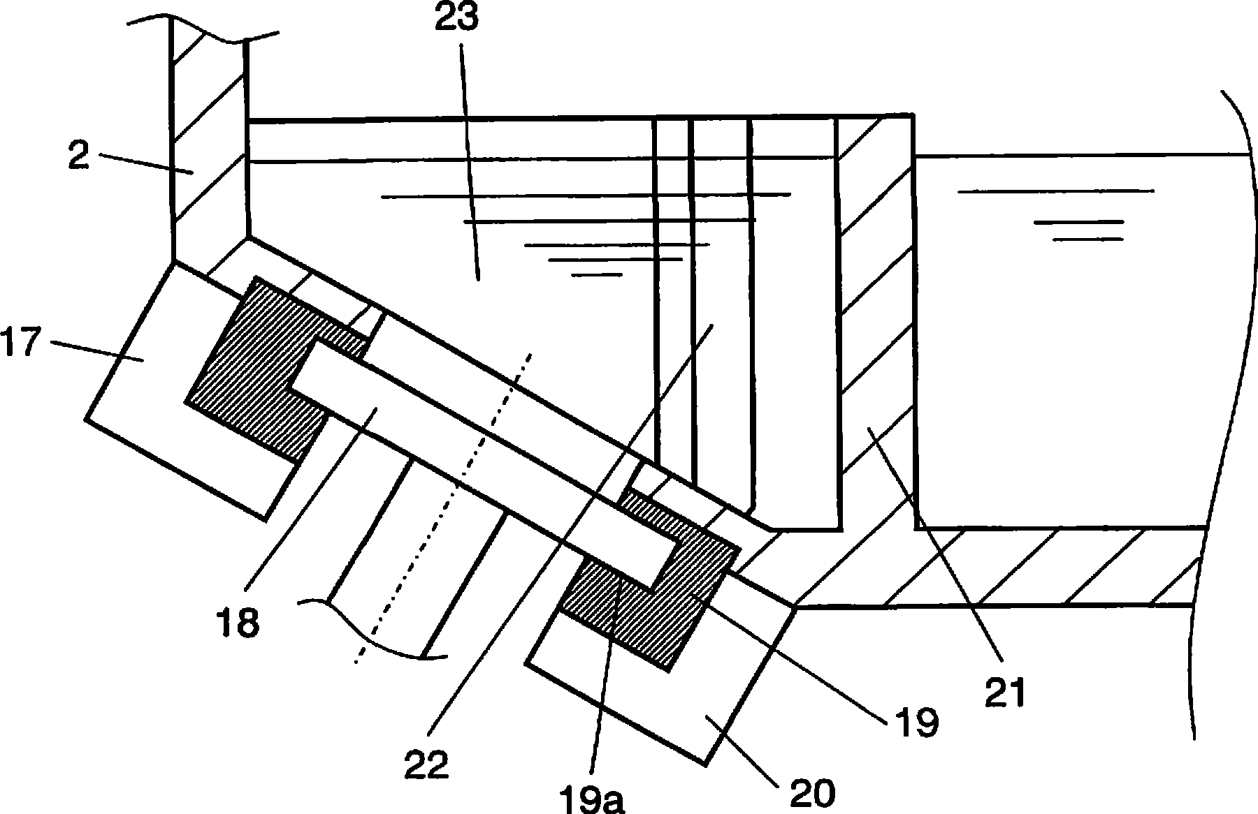
[0019] figure 1 It is a vertical cross-sectional view of a dishwasher according to an embodiment of the present invention, figure 2 and image 3 It is a sectional view of main parts of the dishwasher. exist Figure 1 ~ Figure 3 Among them, the main body 1 of the dishwasher is provided with a washing tank 2 for accommodating objects to be cleaned such as tableware. Water or hot water is supplied into the washing tank 2 by a water supply valve 3 . A drainage hole 4 is provided at the bottom of the cleaning tank 2 . A washer pump 5 driven by a motor (not shown) is installed in communication with the drain hole 4 . Washing water is circulated in the wash...


PUM


Abstract

The present invention provides a dishware cleaning device comprising a cleaning groove (2) an opening section (2b) and an ultrasonic resonator (18), the cleaning groove (2) contains articles to be cleaned inside, the opening section (2b) is arranged on bottom of the cleaning groove (2b), the ultrasonic resonator (18) is arranged inside the opening section (2b), cleaning water supplied to the cleaning groove (2) is atomized, the ultrasonic resonator (18) slants to make the center of a vibration face higher than lowest section (2c) of higher opening end periphery of the opening section (2b), such that the opening section (2b) facing the inside of the cleaning groove (2) is arranged on bottom of the cleaning groove (2), the invention has above structure, thereby preventing residual offscourings from effecting action of the ultrasonic resonator (18).

Description

technical field [0001] The invention relates to a tableware cleaning machine for cleaning objects to be cleaned such as tableware. Background technique [0002] use Figure 4 For example, a conventional general dishwasher disclosed in JP 2003-210378 A will be described. Such as Figure 4 As shown, the conventional dishwasher 1 is provided with a washing tank 13 inside, and water or hot water is supplied into the washing tank 13 through the water supply valve 3 . A drain hole 4 is provided at the bottom of the cleaning tank 13 . A washer pump 5 driven by a motor (not shown) is installed in communication with the drain hole 4 . Washing water is circulated in the washing tank 13 by the washing pump 5 . Furthermore, the drain hole 4 has a residue filter 6 for trapping residue (scum). [0003] In the above structure, the washing water supplied into the washing tank 13 is sucked into the washing pump 5 through the residue filter 6 . After that, it is supplied to the cleaning ...

Claims


Application Information

Patent Timeline
IPC IPC(8): A47L15/13A47L15/42
CPCA47L15/0055A47L15/44A47L2401/09A47L2501/01A47L2501/07A47L2501/36A47L2601/17A47L15/13A47L15/42
Inventor 宫内隆中野博之
Owner PANASONIC CORP
Why Eureka
Try Eureka