Forming method of hot rolling device and double-sided microstructure optical membrane

A technology of optical film and hot rolling, which can be applied to applications, household appliances, flat products, etc., and can solve the problem of uneven brightness of liquid crystal panels

Inactive Publication Date: 2009-06-10
IND TECH RES INST
View PDF0 Cites 12 Cited by
  • Summary
  • Abstract
  • Description
  • Claims
  • Application Information

AI Technical Summary

Problems solved by technology

In this case, the light cannot be effectively guided by the light guide plate to the LCD panel, resulting in uneven brightness of the LCD panel

Method used


Image

  • Forming method of hot rolling device and double-sided microstructure optical membrane
  • Forming method of hot rolling device and double-sided microstructure optical membrane
  • Forming method of hot rolling device and double-sided microstructure optical membrane

Examples


Embodiment Construction

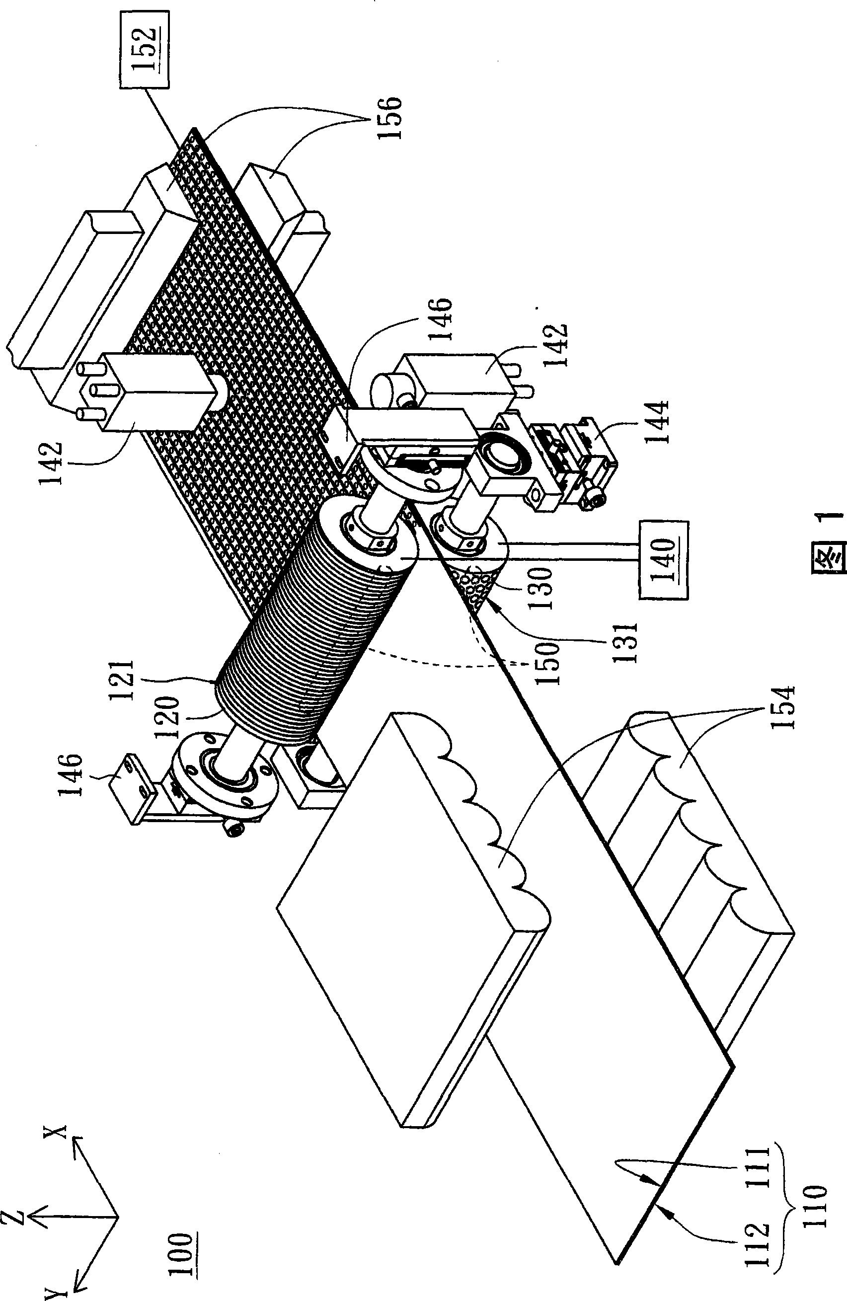
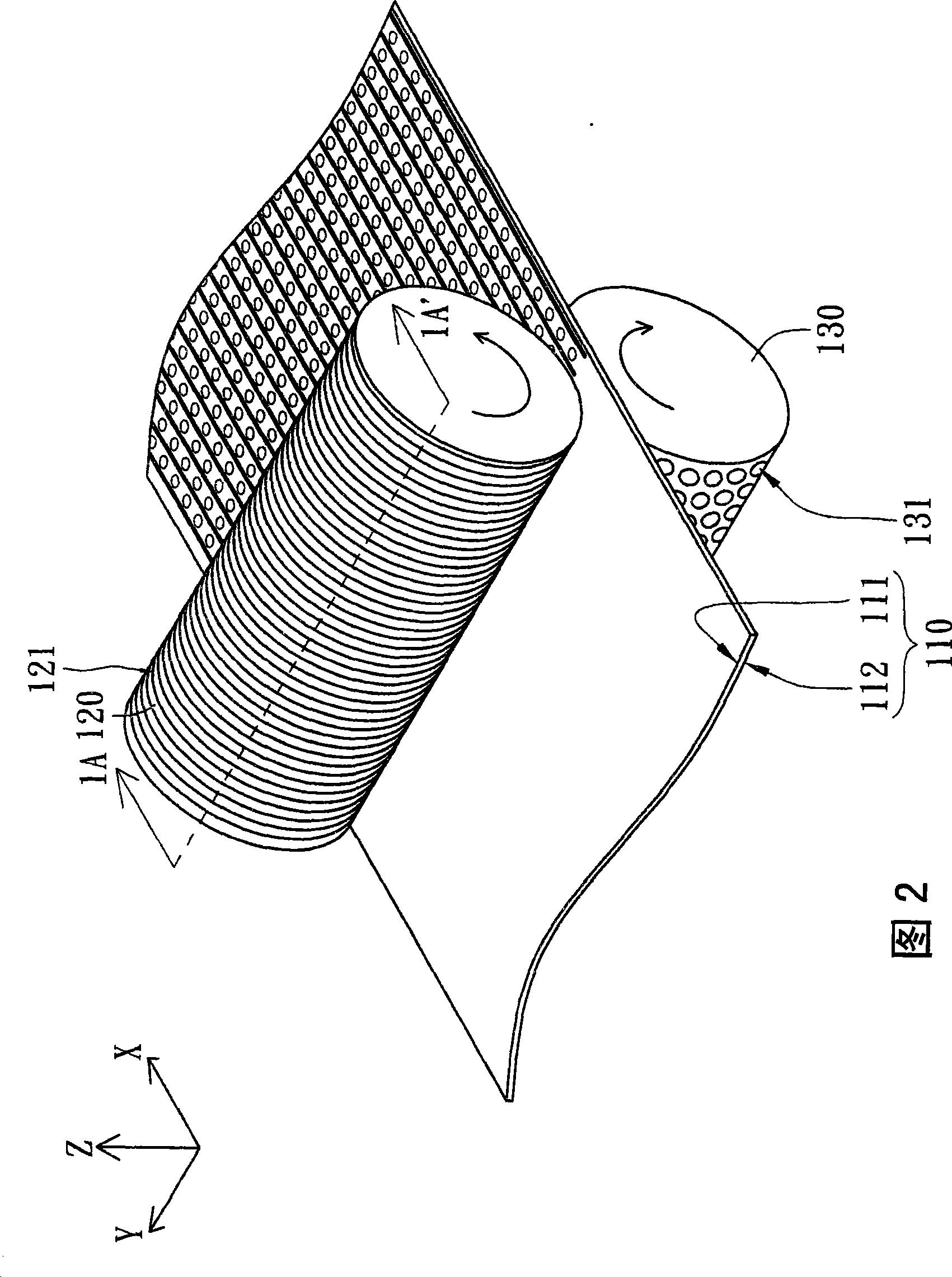
[0061] Please refer to FIG. 1 and FIG. 2 at the same time. FIG. 1 shows a schematic diagram of a thermal rolling device 100 according to a preferred embodiment of the present invention. FIG. 2 shows the first roller 120, the second roller 130 and the optical An enlarged view of diaphragm 110 . For clarity, FIGS. 1 and 2 draw the double-sided microstructures on the optical film 110 with solid lines. As shown in FIG. 1 , the thermal rolling device 100 is used to form double-sided microstructures on a first surface 111 and a second surface 112 of an optical film 110 . The hot rolling device 100 includes a first roller 120 , a second roller 130 and a heating unit 140 . The first roller 120 has a first pattern 121 and the second roller 130 has a second pattern 131 . The first pattern 121 and the second pattern 131 are, for example, one-dimensional or two-dimensional optical microstructure patterns. The heating unit 140 is used for heating the first roller 120 and the second roll...


PUM


Abstract

The invention relates to a hot rolling device and a method for forming a double-sided microstructural optical film. The hot rolling device is used for forming a double-sided microstructure on the first surface and the second surface of the optical film and comprises a first platen, a second platen and a heating unit. The first platen is provided with a first pattern. The second platen is provided with a second pattern. The heating unit is used for heating the first platen and the second platen. When the first platen and the second platen roll, the optical film passes through the middle part between the first platen and the second platen. The first platen and the second platen are contacted with and pressed on the first surface and the second surface respectively so that the first surface forms the first pattern and the second surface forms the second pattern.

Description

technical field [0001] The present invention relates to a thermal rolling device and a method for forming a double-sided microstructured optical film, and in particular to a thermal rolling device with process continuity and a method for forming a double-sided microstructured optical film . Background technique [0002] MEMS and microstructure film core products are widely used in electronic products, such as liquid crystal display devices or light guide plates or optical display films of mobile phones. Taking a thin film transistor (Thin Film Transistor, TFT) liquid crystal display device as an example, the light guide plate of the backlight module is used to guide light so that the liquid crystal panel exhibits uniform brightness. [0003] When light enters the light guide plate with a polished surface, the light travels back and forth in the light guide plate until the energy of the light is completely attenuated. In this case, light cannot be effectively guided by the ...

Claims


Application Information

Patent Timeline
Patent Type & Authority Applications(China)
IPC IPC(8): B29C59/04B29C35/16B29K69/00B29K33/04B29K67/00B29L7/00
Inventor 黄超俊林宏彝徐达伟张复瑜
Owner IND TECH RES INST
Why Eureka
Try Eureka