
Joining column structure

A technology of combining columns and joints, applied in the direction of connecting components, threaded fasteners, nuts, etc., can solve the problems of shell depression, poor surface flatness and aesthetics of the shell, etc.

Inactive Publication Date: 2009-06-10
INVENTEC CORP
View PDF0 Cites 0 Cited by
  • Summary
  • Abstract
  • Description
  • Claims
  • Application Information

AI Technical Summary

Problems solved by technology

[0006] The technical problem to be solved by the present invention is to provide a combination column structure, so as to improve the plastic shell in the prior art when the plastic shell is formed by injection molding. Because the contact area between the fixed column and the shell is too large, the shell will shrink due to mold shrinkage. and the influence of assembly stress to produce serious depressions, resulting in poor flatness and aesthetics of the shell surface

Method used


Image

  • Joining column structure
  • Joining column structure
  • Joining column structure

Examples


Embodiment Construction

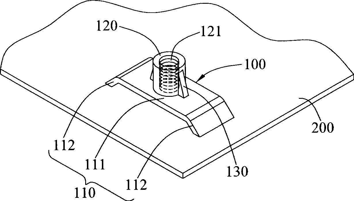
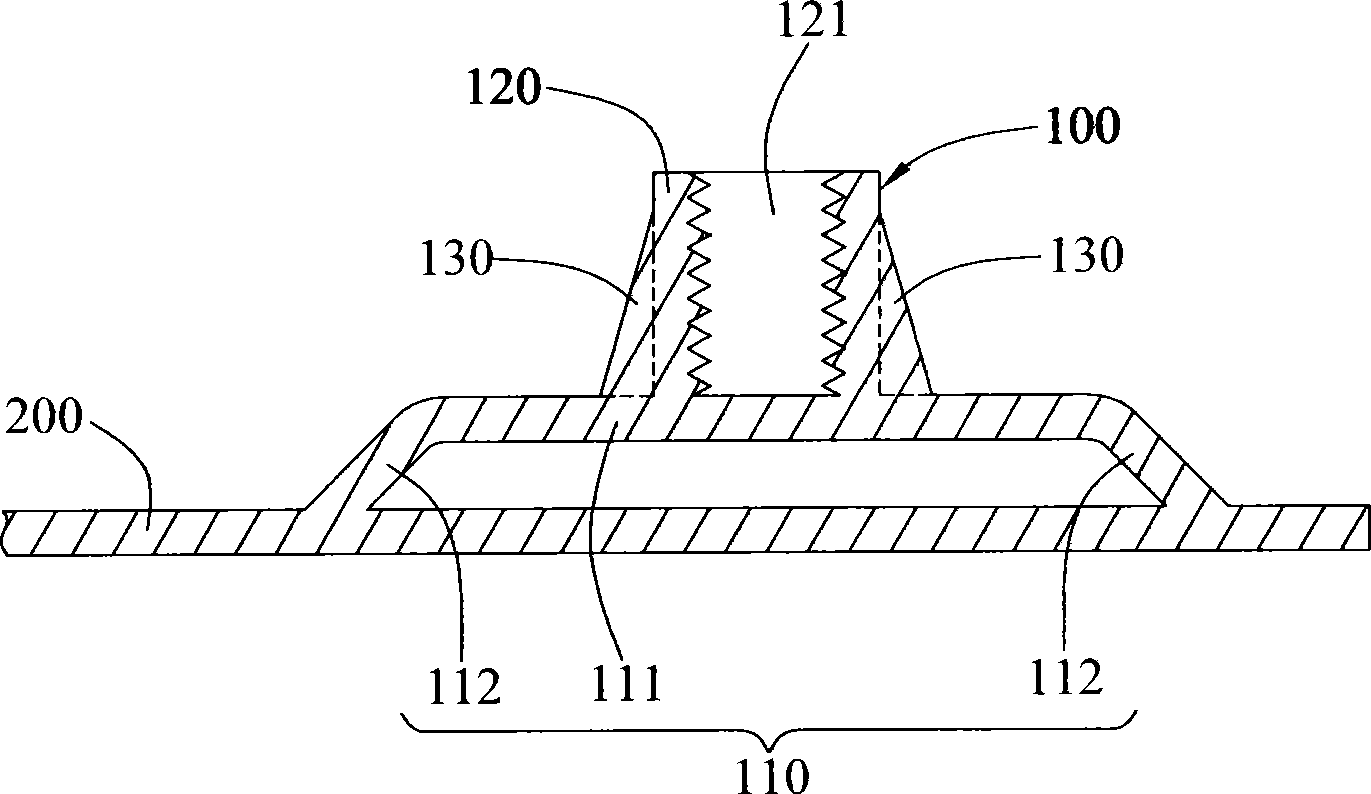
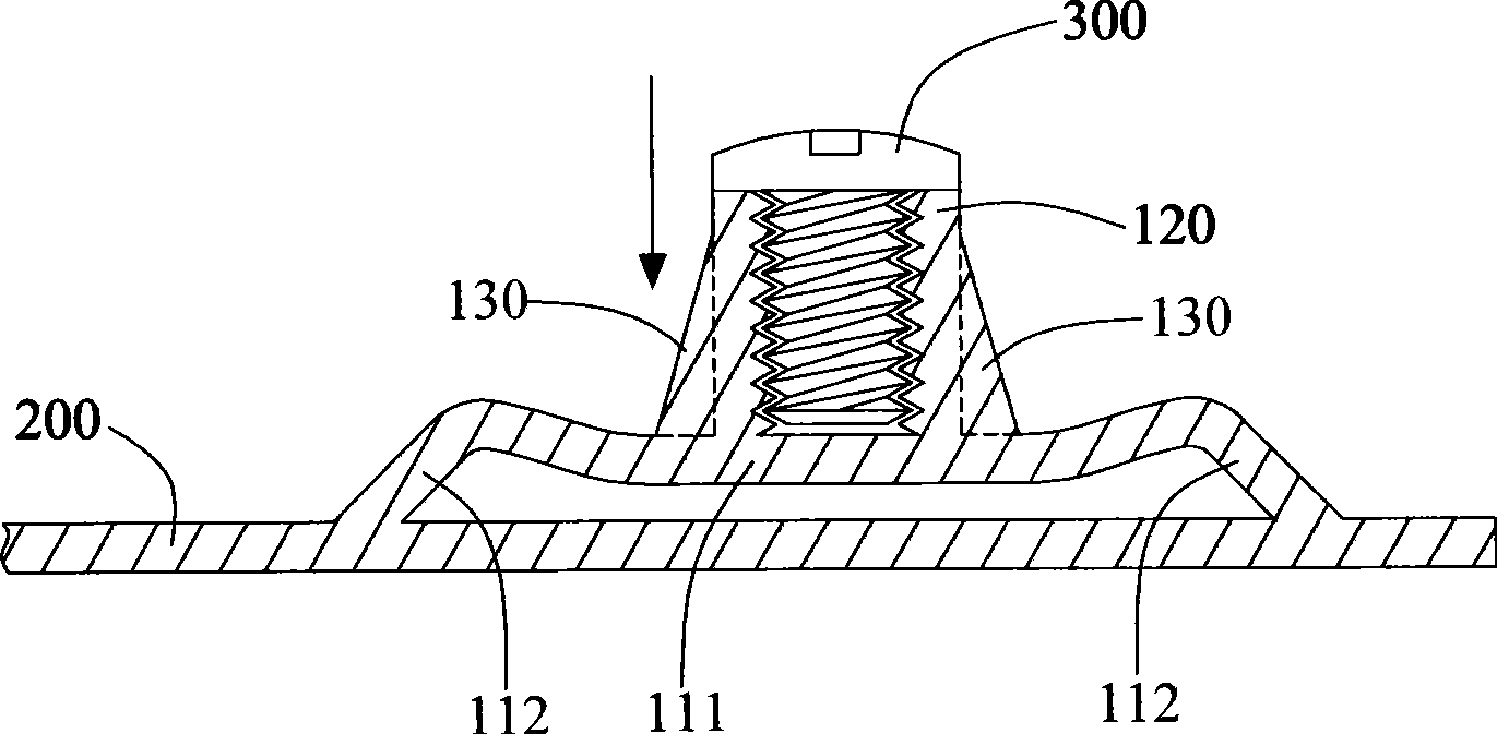
[0019] see figure 1 and figure 2 The coupling column structure 100 of the present invention is formed on a housing 200 in an integral and inseparable relationship, for example, the coupling column 100 is formed on the housing 200 by plastic injection molding, so that the coupling column 100 and the housing 200 are integrally formed structure.

[0020] The coupling post 100 includes a suspension 110 and a coupling 120. The suspension 110 has a bearing part 111 of a flat plate structure, and a connecting part 112 is respectively extended from two opposite sides of the bearing part 111, and the two connecting parts 112 It is connected to the housing 200 at an inclined angle, so that the bearing part 111 is suspended on the housing 200 with a distance from the housing 200 .

[0021] The coupling part 120 is a cylindrical structure integrally formed with the suspension part 110 , and a screw hole 121 is provided at the top of the coupling part 120 . The coupling part 120 is dis...


PUM


Abstract

The invention discloses a combined column structure, which is integrally and inseparably formed on a shell. The combined column comprises a suspension element and a combined element which is formed on the suspension element. Two ends of the suspension element are connected with the shell, so that the suspension element and the shell are separated by an interval, and the combined element does not contact the shell. The combined element is suspended on the shell through the suspension element, but does not contact the shell, so as to reduce contact area of the combined column and the shell, and improve the problems of concave and unevenness of the shell surface caused by molding shrinkage when the combined column is formed on the shell.

Description

technical field [0001] The invention relates to a combination column structure, in particular to a combination column structure formed on a housing in an integral and inseparable relationship. Background technique [0002] In recent years, plastic materials have been widely used in various industries due to their advantages such as low price, light weight, and easy mass production. [0003] Currently seen plastic products, such as plastic casings of portable computer devices, are mostly made by plastic injection molding. However, when the liquid plastic is solidified to form a solid plastic product, its volume will shrink due to the closure of the gate or insufficient plastic injection, and a depression will be formed on the plastic product corresponding to the position of the gate, which is the current plastic product. The shrinkage phenomenon is the most difficult to overcome in the injection molding process. [0004] Taking the plastic case of a portable computer device...

Claims


Application Information

Patent Timeline
IPC IPC(8): G06F1/18F16B37/00H05K5/02
Inventor 阮贤伟孙德彰
Owner INVENTEC CORP
Learn More