Part flattening system and method

A technology for parts and feature files, applied in the field of part flattening systems, can solve problems such as reduced design efficiency, unrealizable sheet metal design, and inability to flatten sheet metal parts, and achieves the effect of improving work efficiency

Inactive Publication Date: 2009-06-10
HONG FU JIN PRECISION IND (SHENZHEN) CO LTD +1
View PDF0 Cites 0 Cited by
  • Summary
  • Abstract
  • Description
  • Claims
  • Application Information

AI Technical Summary

Problems solved by technology

However, if the stamping position happens to intersect with the bending surface of the sheet metal part, the program of the commonly used 3D model design software system itself cannot flatten the sheet metal part, so many sheet metal part designs cannot be realized. Efficiency will also decrease as a result

Method used


Image

  • Part flattening system and method
  • Part flattening system and method
  • Part flattening system and method

Examples


Embodiment Construction

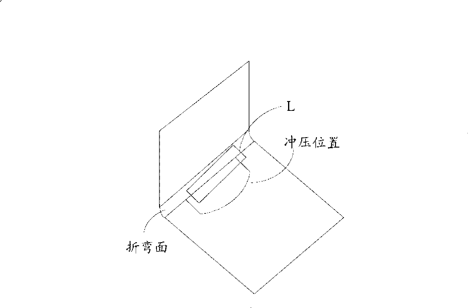
[0010] The part described in the part flattening system and method of the present invention refers to a part that satisfies the following characteristics: the stamping position of the part intersects the bending surface of the part.

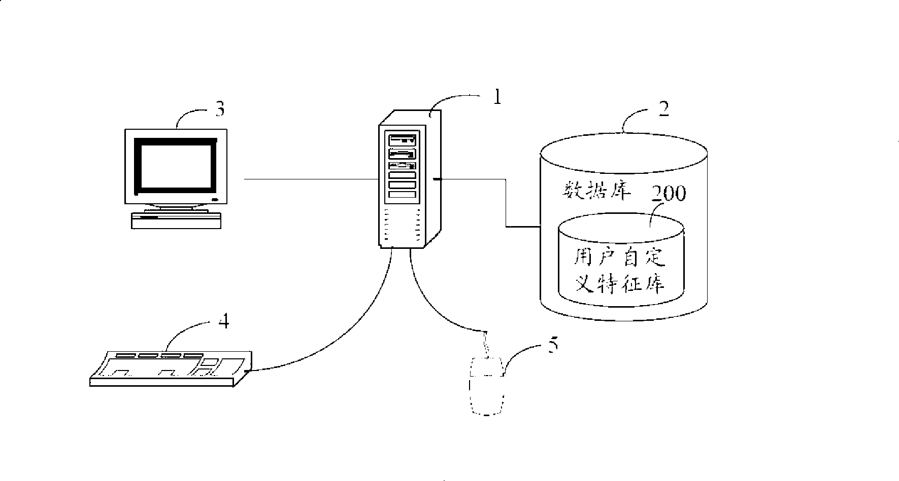
[0011] Such as figure 1 Shown is a hardware architecture diagram of a preferred embodiment of the parts flattening system of the present invention. The system includes a host 1 and a database 2 connected to it. Among them, host machine 1 is used to cut parts and flatten them. This database 2 is used for storing the sketch characteristic curve, and described sketch characteristic curve is closed, and this sketch characteristic curve comprises the sketch characteristic curve on XY plane, XZ plane, YZ plane, and this sketch characteristic curve is located The orientation of the plane is fixed. The database 2 also includes a user-defined feature (User Defined Feature, UDF) library 200, the user-defined feature library 200 stores different feature ...


PUM


Abstract

The invention relates to a component flattening method, which comprises: selecting one surface of a component to be a reference surface of the component; selecting a sketch characteristic curve of the component, taking the surface on which the sketch characteristic curve is positioned as a cross section for creating incision characteristics, and selecting a stretching mode for the sketch characteristic curve; acquiring the stretching depth inputted by a user, and acquiring an incision characteristic file from a user-defined characteristic library, wherein the incision characteristics of the component are created at the moment and comprise edge arrays of the incision characteristics, and all the edges of incisions are stored into the incision characteristic edge arrays; acquiring two adjacent surfaces of various edges, and acquiring the surface type and the profile number of the two adjacent surfaces of the various edges; selecting an adjacent surface of which the surface type is cylindrical surface and the profile number is at least two, and setting the adjacent surface as a bending surface; and acquiring a flattening characteristic file, and creating flattening characteristics of the component on the reference surface according to the bending surface. Moreover, the invention also provides a component flattening system.

Description

technical field [0001] The invention relates to a part flattening system and method. Background technique [0002] In 3D sheet metal mold design, stamping forming process will be introduced. In general, during the bending and flattening operation of a sheet metal part, the position of the stamping has a significant impact on the successful unfolding of the sheet metal part. As far as the currently commonly used 3D model design software system is concerned, if the punching position is on a certain plane of the sheet metal part, it can be unfolded by calling its sheet metal unfold command. However, if the stamping position happens to intersect with the bending surface of the sheet metal part, the program of the commonly used 3D model design software system itself cannot flatten the sheet metal part, so many sheet metal part designs cannot be realized. Efficiency will also be reduced as a result. Contents of the invention [0003] In view of the above, it is necessary to p...

Claims


Application Information

Patent Timeline
Patent Type & Authority Applications(China)
IPC IPC(8): G06F17/50
Inventor 陈曦
Owner HONG FU JIN PRECISION IND (SHENZHEN) CO LTD
Why Eureka
Try Eureka