Supercharge Your Innovation With Domain-Expert AI Agents!

Device and method for detecting rotary position of to-and-fro piston engine crankshaft

A technology of rotating position and reciprocating piston, which is applied in the direction of engine control, machine/engine, mechanical equipment, etc., and can solve problems such as indirect detection distortion

Inactive Publication Date: 2013-08-21
MAN B & W DIESEL AS
View PDF2 Cites 0 Cited by
  • Summary
  • Abstract
  • Description
  • Claims
  • Application Information

AI Technical Summary

Problems solved by technology

[0005] Another disadvantage of the above-mentioned known solutions lies in the determination of the measuring position: if the measuring position is arranged directly on the crankshaft, as in DE 103 04 699 A1, a higher measuring accuracy is caused due to the small lever arm
Conversely, if the position of the piston is detected as in DE 10 2005 054 627 A1, in particular the play between the piston and the crank can distort the only indirect detection of the rotational position of the crankshaft in this respect.

Method used


Image

  • Device and method for detecting rotary position of to-and-fro piston engine crankshaft

Examples


Embodiment Construction

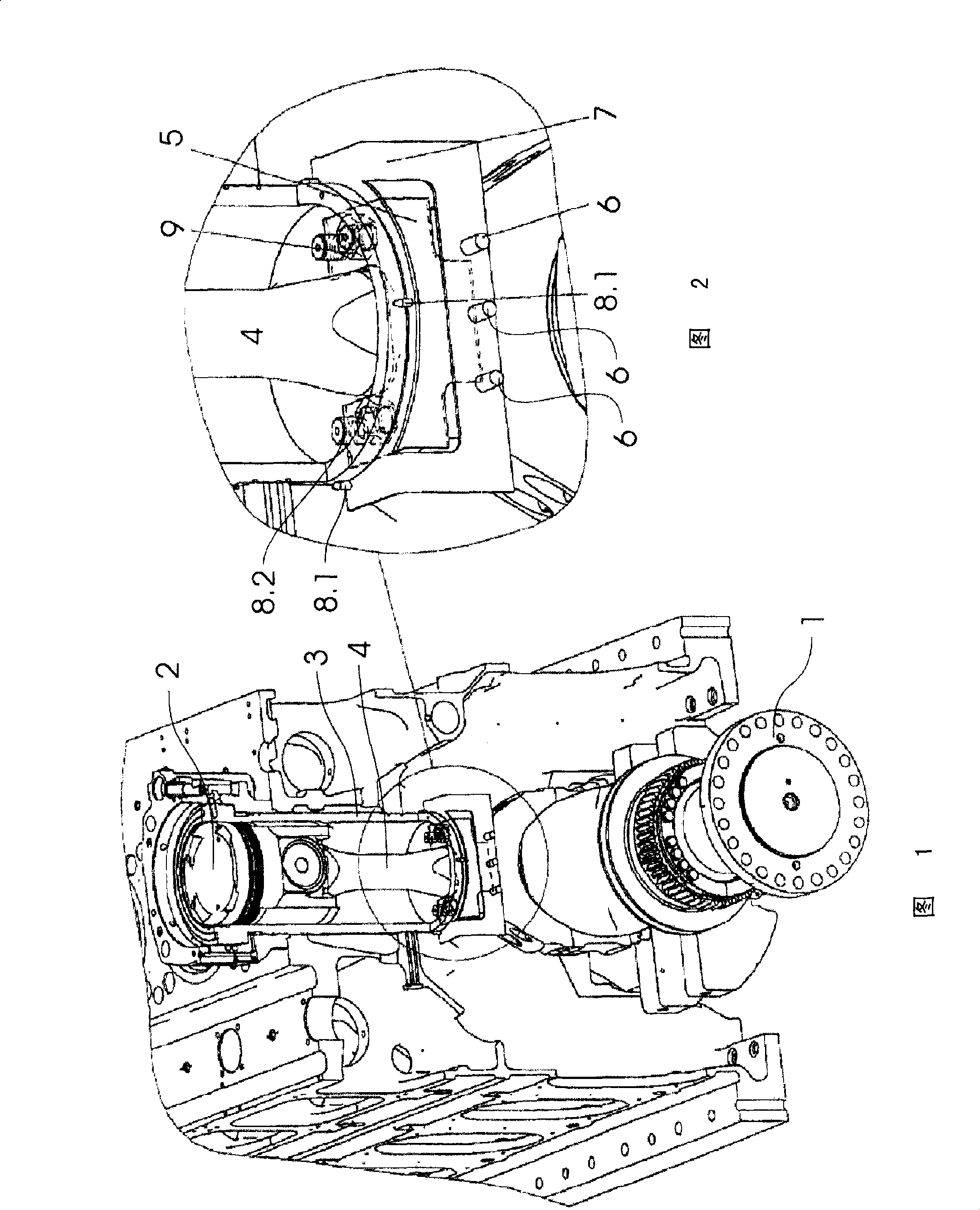
[0040] figure 1 A perspective partial sectional view, with some components removed for clarity, shows a reciprocating piston engine with a crankshaft 1 and a piston 2 movable in a cylinder 3 . The piston is connected to the crankshaft 1 through the crank 4, so that the piston 2 moves up and down in the cylinder when the crankshaft rotates. If piston 2 occupies its farthest position from crankshaft 1 in cylinder 3, then crankshaft 1 is at its figure 1 at the top dead center shown.

[0041] The reciprocating piston engine includes additional cylinders (not shown) in which corresponding pistons move, wherein the pistons figure 1 The pistons shown in are coupled to the crankshaft 1 offset in such a way that they each occupy their position furthest away from the crankshaft 1 when the crankshaft 1 is in different rotational positions. In this respect, the crankshaft 1 has a top dead center for each cylinder, which can be determined according to the invention by arranging the devi...


PUM


Abstract

The device has a measuring body provided with a piston (2), and a sensor arrangement for detecting a position of the measuring body. The measuring body is fastened to a connecting rod (4). The sensor arrangement is arranged at a sensor carrier, which is attached to a cylinder (3). The measuring body and / or the sensor carrier are fastened i.e. screwed, at the connecting rod and / or cylinder. A centering tool i.e. projection, cooperates with the connecting rod and / or the cylinder in a form-fit manner, and is arranged at the measuring body and / or the sensor carrier. An independent claim is also included for a method for detecting of a rotational position i.e. top dead center, of a crankshaft of a reciprocating piston engine.

Description

technical field [0001] The invention relates to a device according to the preamble of claim 1 for detecting the rotational position, in particular the top dead center, of the crankshaft of a reciprocating piston engine having one or more pistons which pass through the crankshaft and the crankshaft Coupled and moved in cylinders, the invention also relates to a method of detecting the rotational position, in particular the top dead center, of the crankshaft of such a reciprocating piston engine. Background technique [0002] For example, in order to precisely set the injection timing, the so-called top dead center of the crankshaft of the reciprocating engine must be detected as accurately as possible. For this reason, all according to the practice in the enterprise before, the upper dead center is detected by means of a spirit level, and the level instrument is placed on the separation seam between the crankshaft and the counterweight. However, such determinations are relat...

Claims


Application Information

Patent Timeline
Patent Type & Authority Patents(China)
IPC IPC(8): G01M15/06
CPCG01M15/06F02D41/34F02D35/00F02D35/02
Inventor H·海默P·德鲁克米勒
Owner MAN B & W DIESEL AS
Features
  • R&D
  • Intellectual Property
  • Life Sciences
  • Materials
  • Tech Scout
  • Unparalleled Data Quality
  • Higher Quality Content
  • 60% Fewer Hallucinations
Learn More