
Automatic detection method and apparatus for double feeding motor rotor initial position angle

A technology of rotor initial position and doubly-fed motor, which is applied in the control of electromechanical transmission, control of generator, motor control, etc. It can solve the problems of manual operation, error-prone, inconvenient measurement process, etc.

Inactive Publication Date: 2009-06-17
SANY ELECTRIC CO LTD
View PDF0 Cites 17 Cited by
  • Summary
  • Abstract
  • Description
  • Claims
  • Application Information

AI Technical Summary

Problems solved by technology

[0016] However, the disadvantage of the above-mentioned prior art is that manual operation, additional equipment and power supply are required, the measurement process is very inconvenient, and errors are prone to occur

Method used


Image

  • Automatic detection method and apparatus for double feeding motor rotor initial position angle
  • Automatic detection method and apparatus for double feeding motor rotor initial position angle
  • Automatic detection method and apparatus for double feeding motor rotor initial position angle

Examples


Embodiment 2

[0165] The difference between the device in the second embodiment and the first embodiment is that the device further includes: a rotor voltage vector angle setting unit 18, a rotor current vector angle obtaining unit 19, a constant value setting unit 20, a second comparator 21, and the third comparator 22 .

[0166] The rotor voltage vector angle setting unit 18 is used to set the rotor voltage vector angle θ S1 , input to the negative input terminal of the second comparator 21 .

[0167] The rotor voltage vector angle θ given by the rotor voltage vector angle given unit 18 S1 can be equal to a given reference voltage angle θ given .

[0168] The rotor current vector angle acquisition unit 19 is connected to the double-fed motor 2 rotor side circuit for obtaining the rotor current vector angle θ S2 , input to the positive input terminal of the second comparator 21 .

[0169] Preferably, the rotor current vector angle acquisition unit 19 may include: a rotor current senso...

Embodiment 4

[0229] The difference between the device described in Embodiment 4 and Embodiment 3 is that the device further includes: a rotor voltage vector angle setting unit, a rotor current vector angle obtaining unit, a constant value setting unit, a second comparator, and a third comparator device.

[0230] The rotor voltage vector angle setting unit is used to set the rotor voltage vector angle θ S1 , into the negative input of the second comparator.

[0231] The rotor current vector angle acquisition unit is connected to the double-fed motor rotor side circuit and used to obtain the rotor current vector angle θ S2 , into the positive input of the second comparator.

[0232] The constant value setting unit is used for setting a constant value π / 2, which is output to the positive input end of the second comparator and the positive input end of the third comparator.

[0233] The second comparator subtracts the rotor voltage vector angle θ from the constant value π / 2 S1 , plus the r...


PUM


Abstract

The invention provides an automatic detection method for a double-fed motor rotor initial position angle, which comprises that: giving a reference voltage angle theta given, combining with a given reference voltage amplitude V ref to generate a reference voltage vector, transforming the reference voltage vector into driving signals by SVPWM to drive a rotor side PWM convertor, generating alternating current voltage signals to apply on a double-fed motor rotor winding, and obtaining the rotor mechanical angle n*theta rotor of the double-fed motor, obtaining a stator voltage vector angle theta1, subtracting the rotor mechanical angle n*theta rotor and the given reference voltage angle theta given with the stator voltage vector angle theta1, and obtaining the rotor initial position angle theta initial, wherein n is the pole pair number of the double-fed motor. The invention further provides an automatic detection device for a double-fed motor rotor initial position angle. And the automatic detection of the double-fed motor rotor initial position angle can be realized through adopting the method and the device of the invention.

Description

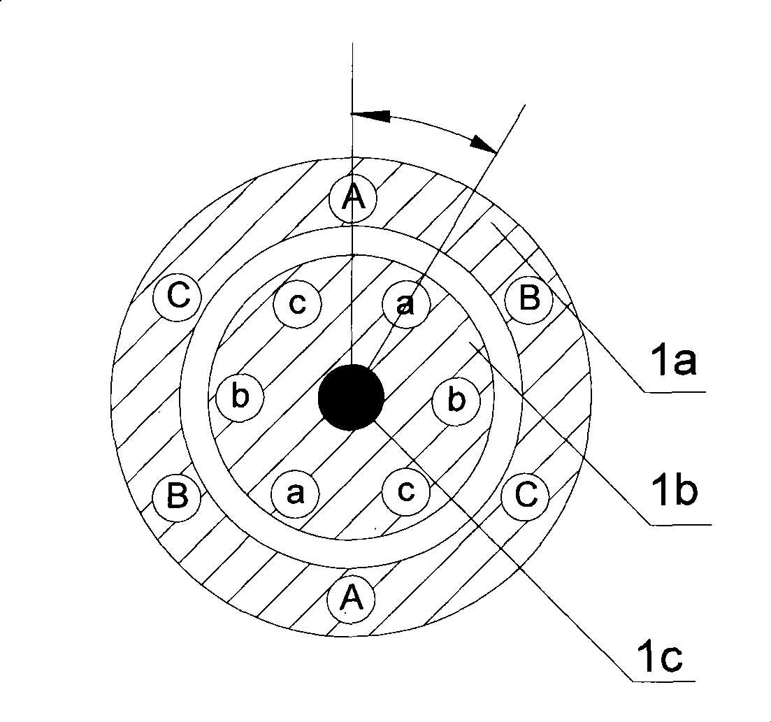
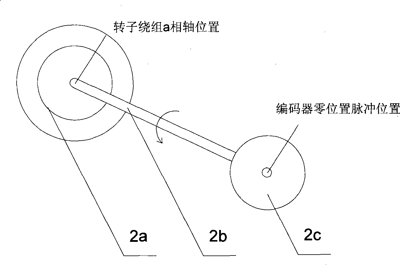
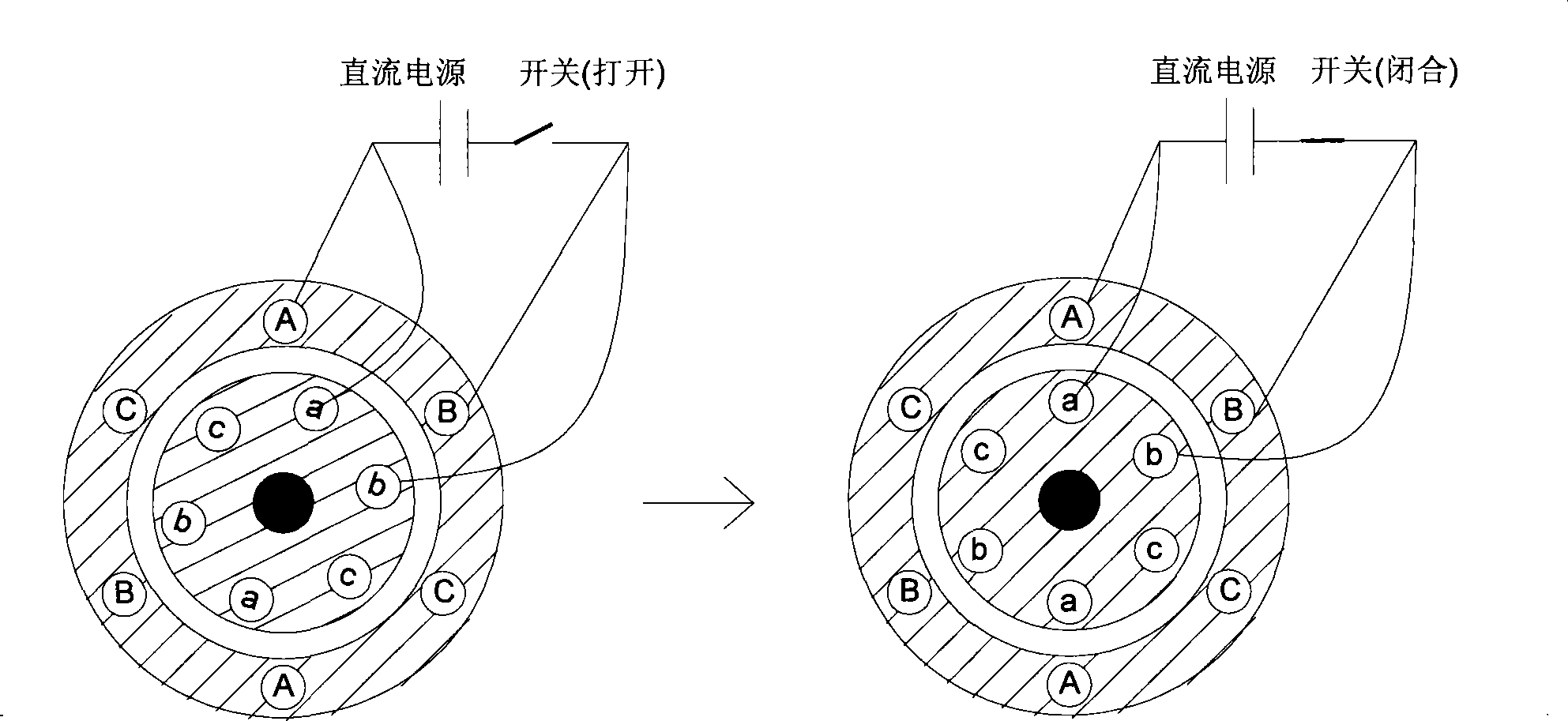
technical field [0001] The invention relates to the field of motor control, in particular to a method and device for automatically detecting the initial position angle of a doubly-fed motor rotor. Background technique [0002] For AC asynchronous motors or synchronous motors, in order to achieve precise torque control, AC motor vector control technology is often used. In order to ensure the accuracy of AC motor vector control, the position angle of the motor rotor winding must be accurately positioned. [0003] see figure 1 , which is a schematic diagram of the rotor winding position angle of a doubly-fed machine. [0004] The doubly-fed machine includes a stator winding 1a, a rotor winding 1b, and a motor shaft 1c. A, B, and C are the three phases of the stator, and a, b, and c are the three phases of the rotor. When the double-fed motor is running, the positions of the three phases of the stator A, B, and C are fixed, while the positions of the three phases of the rotor...

Claims


Application Information

Patent Timeline
Patent Type & Authority Applications(China)
IPC IPC(8): H02P21/00H02P21/14
CPCH02P21/146H02P21/0053H02P9/007H02P2207/073H02P21/18H02P21/32
Inventor 任晓峰魏茹
Owner SANY ELECTRIC CO LTD
Learn More