Optical fiber distributed perturbation sensor and method for implementing perturbation positioning

An optical fiber distribution, disturbance positioning technology, applied in the direction of using optical devices to transmit sensing components, can solve the problems of instability of the output signal amplitude of the interferometer, affecting the reliability of the sensor, etc., and achieve the effect of stabilizing the available amplitude.

Inactive Publication Date: 2009-06-24
BEIHANG UNIV
View PDF0 Cites 14 Cited by
  • Summary
  • Abstract
  • Description
  • Claims
  • Application Information

AI Technical Summary

Problems solved by technology

[0014] Due to the instability of the output signal amplitude of the interferometer, the sensor may fail to have no out

Method used


Image

  • Optical fiber distributed perturbation sensor and method for implementing perturbation positioning
  • Optical fiber distributed perturbation sensor and method for implementing perturbation positioning
  • Optical fiber distributed perturbation sensor and method for implementing perturbation positioning

Examples


Embodiment Construction

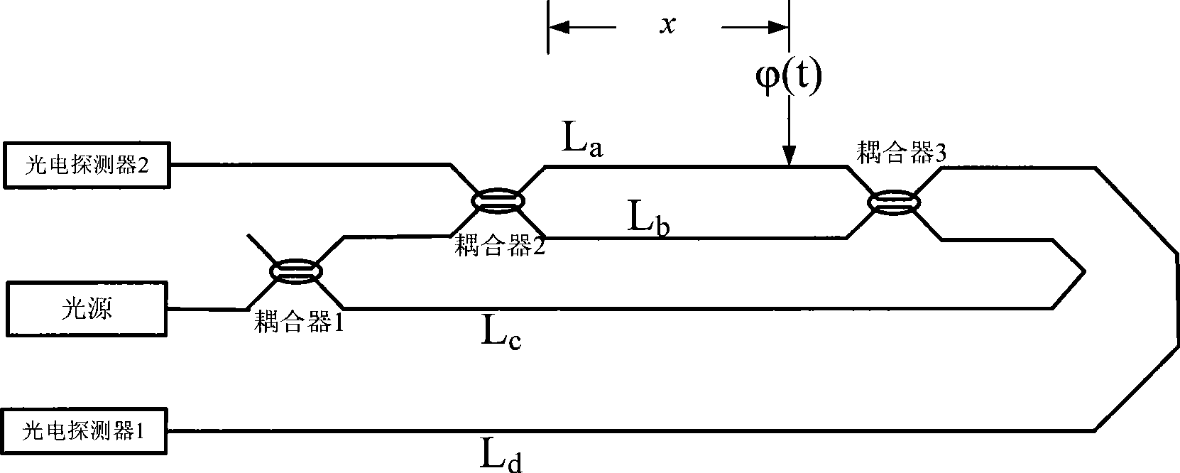
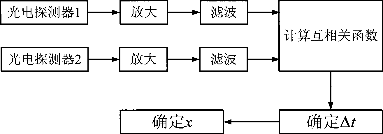
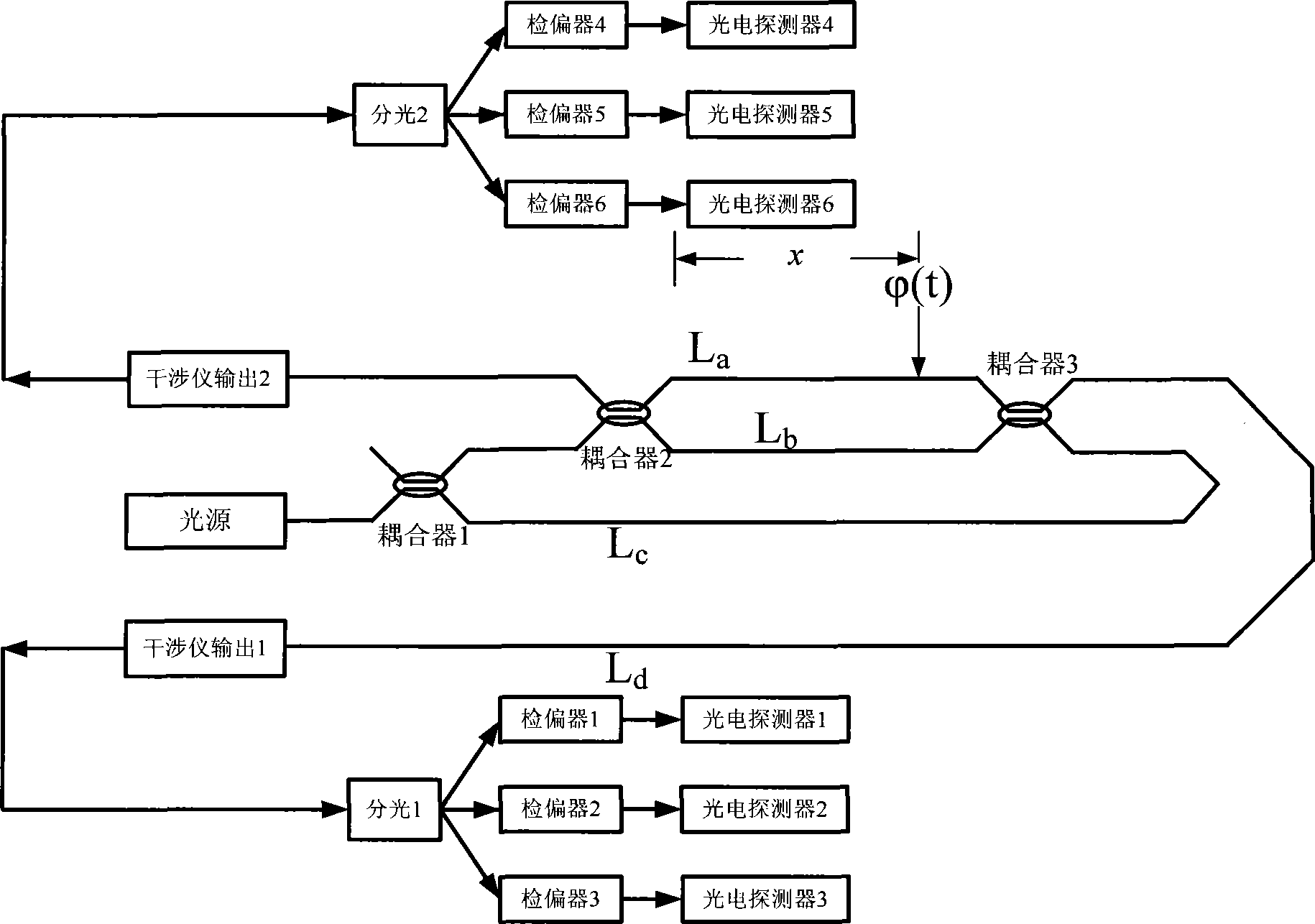
[0026] The optical fiber distributed disturbance sensor of the present invention, its preferred specific embodiment is, comprise the first interferometer, the second interferometer, the output end of the first interferometer and the second interferometer are respectively connected with the beam splitter, the beam splitter The multi-channel output ends are respectively connected with a polarizer, and a photodetector is connected behind the polarizer.

[0027] The output end of the beam splitter can have three channels, correspondingly, each beam splitter is connected with 3 polarizers, and the polarization angle differences of the 3 polarizers are: 0±10 degrees, 60±10 degrees, -60±10 degrees, or 0±10 degrees, 60±10 degrees, 120±10 degrees. According to needs, there may be multiple channels. For the case of n channels, the polarization angles of each analyzer differ by 180 / n degrees respectively.

[0028] Both the first interferometer and the second interferometer are Mach-Zehn...


PUM


Abstract

The invention discloses an optical fiber distributed disturbance sensor, and a method, by which the disturbance sensor can achieve disturbance positioning. The method is characterized in that light path output signals from an interferometer are divided into three equal paths of light, pass through analyzers with polarization angle differences of 0 DEG, 60 DEG and minus 60 DEG respectively, enter a photo detector and are converted to electrical signals therein, are subjected to the square summing calculation after being conditioned by filtered signals and amplified signals, get rid of the DC amount by filtration, and are taken as the final interference output signals for related computation so that disturbance positioning can be carried out. The method can ensure the final interference signals always remain in a certain amplitude range and available, and the possibility of the signals being zero is zero. The invention solves the problem in the prior dual interferometer type distributed disturbance sensor that the sensor doesn't work when the amplitude of the light path output signals of the interferometer changes to zero because of the random variation of the polarization state of light wave.

Description

technical field [0001] The invention relates to an optical fiber sensor, in particular to an optical fiber distributed disturbance sensor and a method for realizing disturbance positioning. Background technique [0002] Optical fiber sensors are widely used in industrial, civil and military fields due to their excellent characteristics such as anti-electromagnetic interference, small size, light weight, high sensitivity, easy networking, and especially the ability to realize distributed measurement. Among them, the optical fiber distributed disturbance sensor is of great significance in the field of perimeter alarm, oil pipeline monitoring and other structural monitoring. [0003] At present, according to the difference of working principle, there are many types of optical fiber distributed sensors, such as interferometer type, fiber grating type, optical time domain reflectometer type, intensity modulation type and scattering type. Among them, the interferometer-type distr...

Claims


Application Information

Patent Timeline
IPC IPC(8): G01D5/26
Inventor 张春熹梁生林文台李琛杨玉生李立京张晞李彦
Owner BEIHANG UNIV
Why Eureka
Try Eureka