Functional rotary table and rotary switch using the same

A rotary switch and turntable technology, applied in the direction of electric switches, electrical components, circuits, etc., can solve the problems of resource consumption, functional turntable shaking, environmental pollution, etc., and achieve the effects of improving reliability, simplifying the process, and reducing costs

Inactive Publication Date: 2009-06-24
HONG FU JIN PRECISION IND (SHENZHEN) CO LTD +1
View PDF0 Cites 3 Cited by
  • Summary
  • Abstract
  • Description
  • Claims
  • Application Information

AI Technical Summary

Problems solved by technology

However, the dial on an ordinary turntable is generally fixed to the rotating base on the switch circuit in the electronic device through screws or glue. When using screws, it is necessary to rotate the dial and the corresponding The position reserved on the base is used to set bolt holes, so that the volume of the functional turntable cannot be reduced, which is not suitable for the development direction of today's electronic devices, which are light, thin and short. At the same time, in today's increasingly scarce resources, the use of screws is undoubtedly increasing. cost, but also consume a lot of resources; when the dial is bonded to the rotating base with glue, the dial cannot be disassembled once it is fixed. If the function dial or the switch corresponding to the function dial If the circuit is damaged, the entire function dial and the corresponding switch circuit can only be replaced, which greatly increases the subsequent maintenance cost of electronic products, and the volatile substances in the glue will cause environmental pollution and endanger human health. , when the viscose is aging, it will have a great impact on the use of the function turntable, such as the shaking of the function turntable, misalignment and other defects will bring great trouble to the user

Method used


Image

  • Functional rotary table and rotary switch using the same
  • Functional rotary table and rotary switch using the same
  • Functional rotary table and rotary switch using the same

Examples


Embodiment Construction

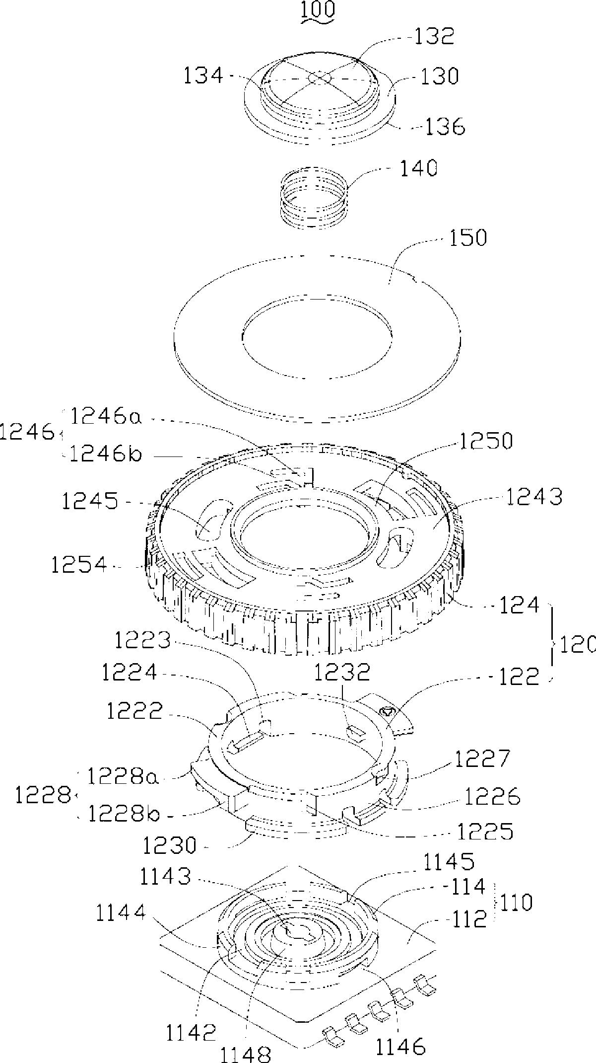
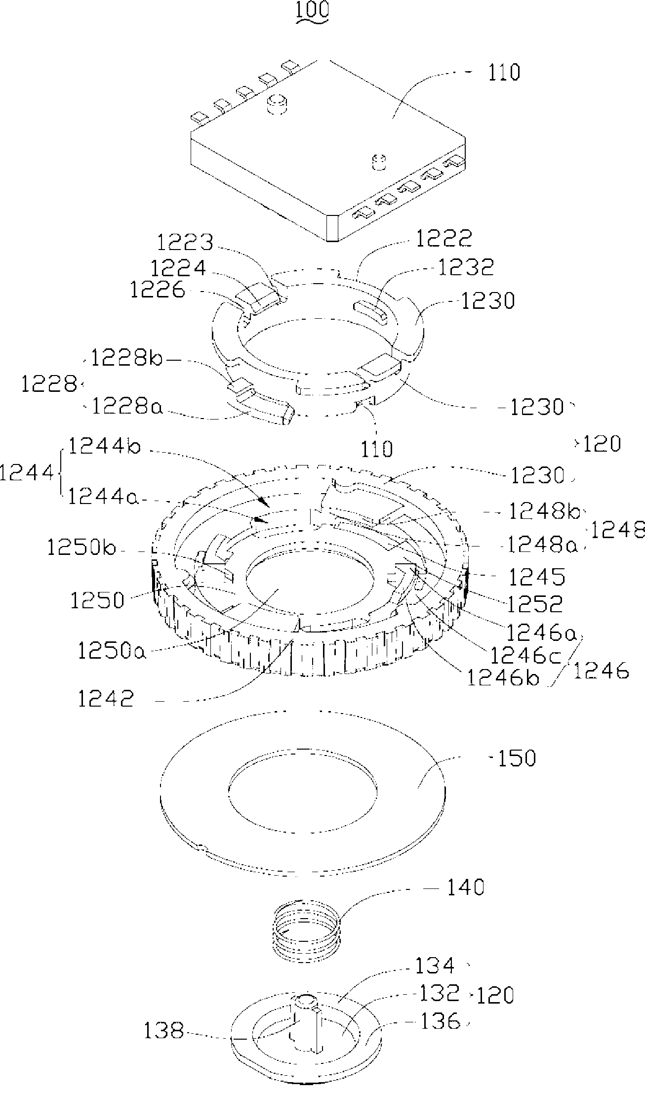
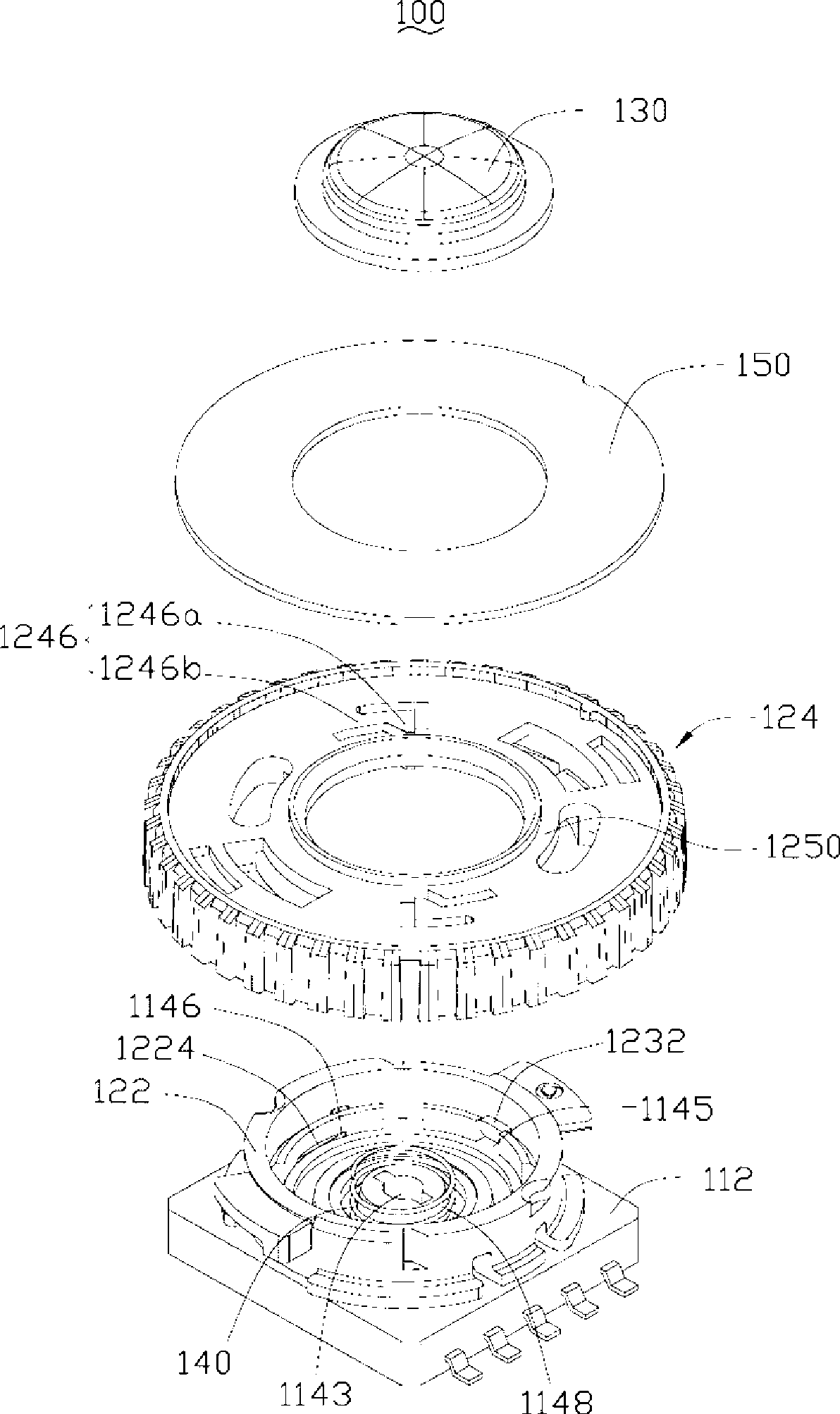
[0014] Please also refer to figure 1 and figure 2 , the rotary switch 100 of the present invention includes a switch module 110 , a function dial 120 arranged on the switch module 110 , a button 130 and a spring 140 .

[0015] The switch module 110 includes a switch box 112 and a rotating base 114 rotatably disposed on the switch box 112 . The switch box 112 is provided with a plurality of switch circuits corresponding to different functions distributed in a ring shape, and a switch circuit arranged in the middle of the ring switch circuit. The rotating base 114 is arranged on the switch box 112 , and can control the on-off of different switch circuits inside the switch box 112 by rotating, so as to activate corresponding different functions. The rotating base 114 includes a circular base 1142 and a ring wall 1144 vertically extending from an outer edge of the base 1142 to one side thereof. Two mutually symmetrical bayonets 1146 are respectively formed at the junction of t...


PUM


Abstract

The invention provides a function turntable, which comprises an inner turntable and an outer turntable. The inner turntable comprises a turntable body; wherein, two mutually symmetrical clasps are formed on the inner wall at one end of the turntable body. Two mutually symmetrical arc-shaped inner locking plates are formed on the outer wall at one end of the clasps and deviated from the turntable body along the radial direction of the inner turntable. Two mutually symmetrical retaining slots are formed on the outer wall at one end of the inner locking plates on the turntable body. The outer turntable comprises a circular rotating body and a circular protruding edge formed at the inner side of one end of the rotating body. Outer locking plates and ratchets respectively matched with the inner locking plates and the retaining slots of the inner turntable are formed respectively on the inner side and the protruding edge of the rotating body. The outer turntable is clamped at one end of the inner turntable, wherein, the inner locking plates of the inner turntable and the outer locking plates of the outer turntable are wedged in each other in a staggered manner; and one end of each ratchet is clamped in each retaining slot. The invention also provides a rotating switch using the function turntable.

Description

technical field [0001] The invention relates to a function turntable, in particular to a function turntable with low cost and reliable installation. The invention also provides a rotary switch using the function dial. Background technique [0002] The function dial is a multi-position selection switch widely used in electronic devices. A general function dial has a dial, which is installed on a rotating base on the switch circuit of the electronic device. The rotating base A plurality of switch circuits integrated on a circular track can be connected according to different functions, and the dial is fixedly connected to the rotating base so as to transmit the user's force to the rotating base to drive the rotating base. The seat rotates to activate different functions of the electronic device. However, the dial on an ordinary turntable is generally fixed to the rotating base on the switch circuit in the electronic device through screws or glue. When using screws, it is nec...

Claims


Application Information

Patent Timeline
IPC IPC(8): H01H19/20H01H19/14
Inventor 蔡智翔杨馥绫高于凯
Owner HONG FU JIN PRECISION IND (SHENZHEN) CO LTD
Why Eureka
Try Eureka