Change-over circuit from CMOS to MCML

A conversion circuit and circuit technology, applied in the direction of logic circuit coupling/interface, logic circuit connection/interface layout, etc. using field effect transistors, can solve power supply noise and output jitter, small output voltage swing, and MCML circuit after Problems such as work performance and speed impact, to solve the effect of switching noise and avoiding delay problems

Active Publication Date: 2009-06-24
SEMICON MFG INT (SHANGHAI) CORP
View PDF1 Cites 4 Cited by
  • Summary
  • Abstract
  • Description
  • Claims
  • Application Information

AI Technical Summary

Problems solved by technology

[0005] The purpose of the present invention is to provide a conversion circuit from CMOS to MCML to solve the problem of needing an additional input signal generation circuit or reference voltage circuit, as well as the problem of large power supply noise and output jitter in traditional conversion circuits and a conversion circuit with a reference voltage circuit The output voltage swing is small and the problem that affects the performance and speed of the subsequent MCML circuit

Method used


Image

  • Change-over circuit from CMOS to MCML
  • Change-over circuit from CMOS to MCML
  • Change-over circuit from CMOS to MCML

Examples


Embodiment Construction

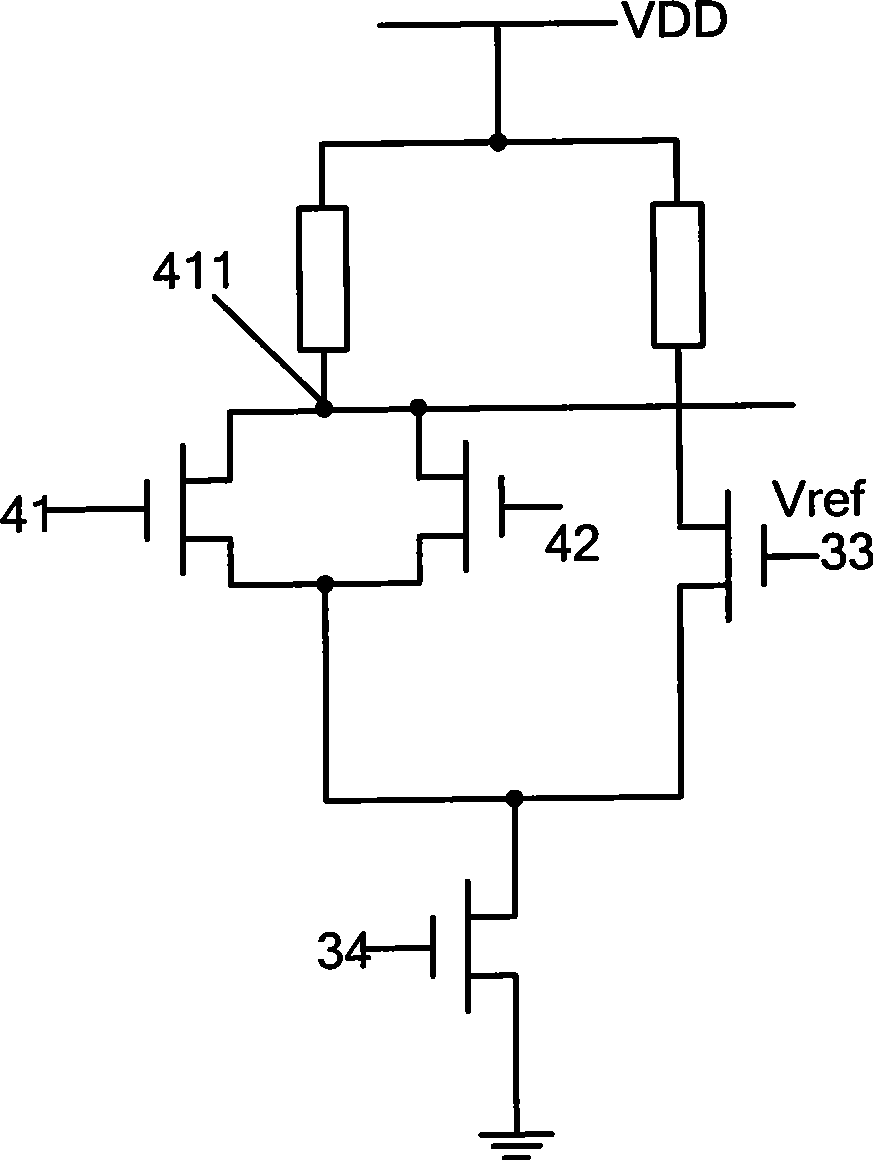
[0020] In the conversion circuit from CMOS to MCML of the present invention, CMOS is a single-end output circuit, and MCML is a double-end input circuit. see Figure 5 , the conversion circuit consists of a differential circuit, including a pair of differential transistors N1 and N2, a pair of load resistors R 1 and R 2 , and the bias tube N5, wherein the differential tube N1 / N2 has three terminals: an input terminal, an output terminal and a connection terminal, and the bias tube N5 has three terminals. The input terminal 71 of the differential transistor N1 is connected to the CMOS output signal, the output terminal 712 of the differential transistor N1 is connected to the input terminal 72 of the differential transistor N2, and the output terminal 712 of the differential transistor N1 and the output terminal 722 of the differential transistor N2 are respectively connected to two MCML The input terminal is connected; one end of the load resistor R1 / R2 is connected to the p...


PUM


Abstract

The invention provides a CMOS-MCML conversion circuit, which is used for the conversion between a single-end output CMOS circuit and a double-end input MCML circuit. The conversion circuit is composed of a differential circuit which comprises a pair of differential tubes, a pair of loads and an offset tube; the input end of a differential tube of the pair of differential tubes is connected with the output end of the CMOS, and the output end of the differential tube is connected with the input end of the other differential tube; the output ends of the pair of differential tubes are used as two input ends of the MCML circuit. As the output end of a differential tube is used as the input end of the other differential tube, an extra signal generating circuit is effectively saved; the problems of power supply noise, output jitter and high conversion noise found in traditional differential circuit are effectively reduced; the problem that when the input end of a differential tube introduces external reference voltage, the output voltage has small swing, affects the work performance of subsequent MCML circuit and reduces the circuit speed is solved.

Description

technical field [0001] The invention relates to the design field of conversion circuits between different types of circuits, in particular to a conversion circuit from CMOS to MCML. Background technique [0002] At present, CMOS (Complimentary MOS) is a very common type of logic circuit used in digital logic circuits. Since CMOS circuits have negligible quiescent current, this makes them dominant in digital integrated circuits. In digital logic circuits, MOS current mode logic circuits (MOS Current Mode Logical) have faster speed, lower power consumption and stronger immunity to power supply noise than CMOS circuits in the application of high-speed circuit systems. These advantages make MCML circuits have a dominant position in the design of high-speed and high-performance integrated circuits. However, in the system on a chip (SOC) design, in order to obtain a high-performance SOC at a lower cost, both CMOS circuits and MCML circuits are applied. [0003] In this way, it ...

Claims


Application Information

Patent Timeline
IPC IPC(8): H03K19/0175H03K19/0185
Inventor 杨家奇邓志兵喻骞宇郭俊涛
Owner SEMICON MFG INT (SHANGHAI) CORP
Why Eureka
Try Eureka