Ultrasonic therapy head

A technology of ultrasonic therapy and ultrasonic transducer, which is applied in ultrasonic therapy, medical treatment, ultrasonic/sonic/infrasonic diagnosis, etc. It can solve problems such as damage, difficult maintenance, and large size, and achieve the effect of preventing thermal burns and ensuring normal use

Active Publication Date: 2009-07-01
RONGHAI SUPERSONIC MEDICINE EN
View PDF1 Cites 34 Cited by
  • Summary
  • Abstract
  • Description
  • Claims
  • Application Information

AI Technical Summary

Problems solved by technology

However, the water circulation cooling device has shortcomings such as easy aging and damage of pipelines, difficult maintenance, and large volume, and the sealing problem of circulating water is also a difficult problem that has been plaguing the entire ultrasonic therapy field.

Method used


Image

  • Ultrasonic therapy head
  • Ultrasonic therapy head
  • Ultrasonic therapy head

Examples


Embodiment 1

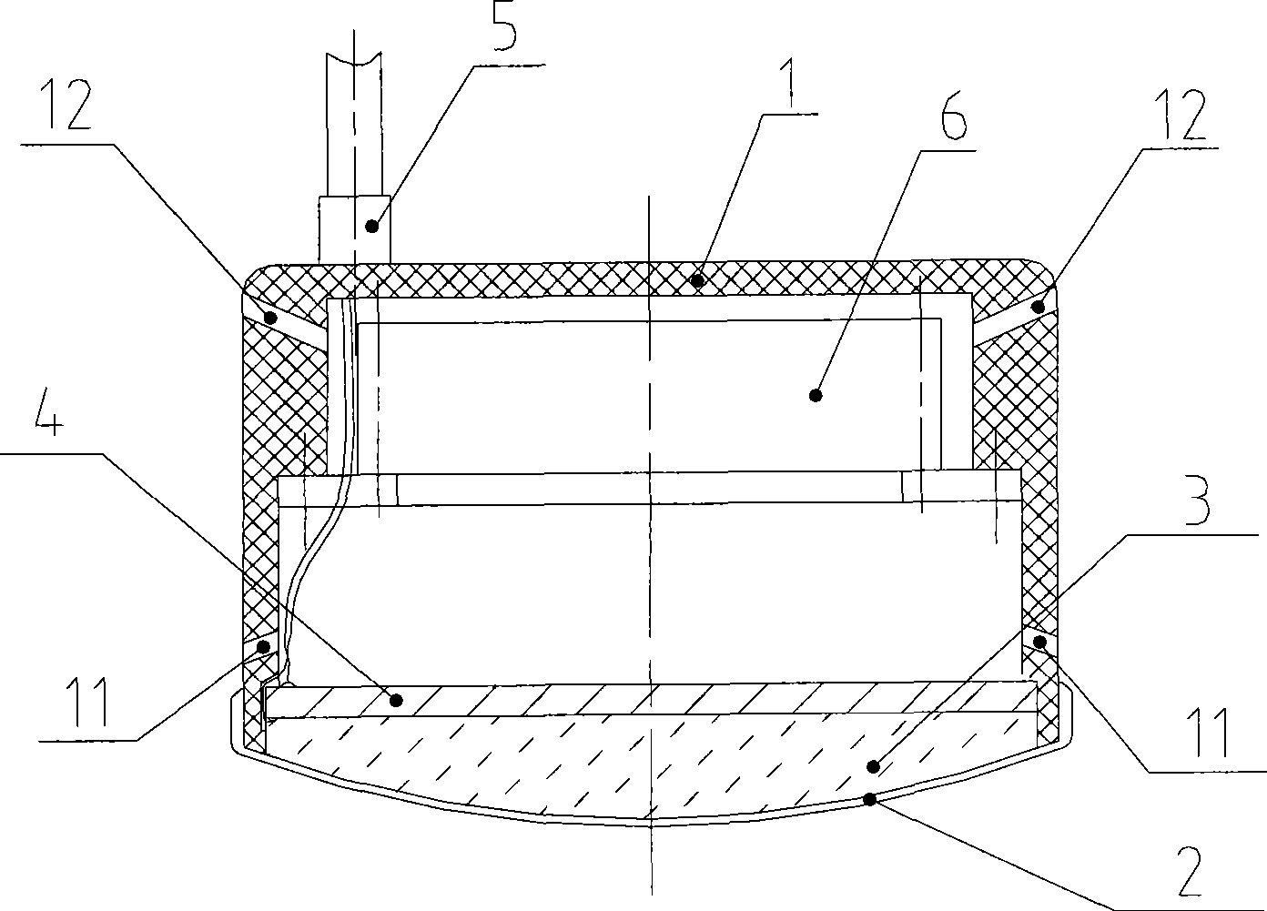
[0025] like figure 1 As shown, the ultrasonic treatment head of the present invention includes a casing 1, and an ultrasonic transducer 4 and a cooling unit are arranged in the casing 1. The casing 1 adopts a structure with a top opening and a certain cavity inside, and the opening is closed by an energy-conducting window 2. Ultrasonic waves emitted by the ultrasonic transducer 4 are emitted outward through the energy-conducting window 2 .

[0026] In this embodiment, the energy-guiding window 2 seals the opening of the housing 1 , and the energy-guiding window 2 is made of rigid or flexible sound-transmitting material with a smooth surface. The ultrasonic transducer 4 adopts a planar ultrasonic transducer and is installed near the open end of the shell 1 near the energy-conducting window 2. The emitting surface of the ultrasonic transducer 4 faces the energy-conducting window 2 to emit therapeutic ultrasonic waves.

[0027] An air inlet 12 and an air outlet 11 are also provi...

Embodiment 2

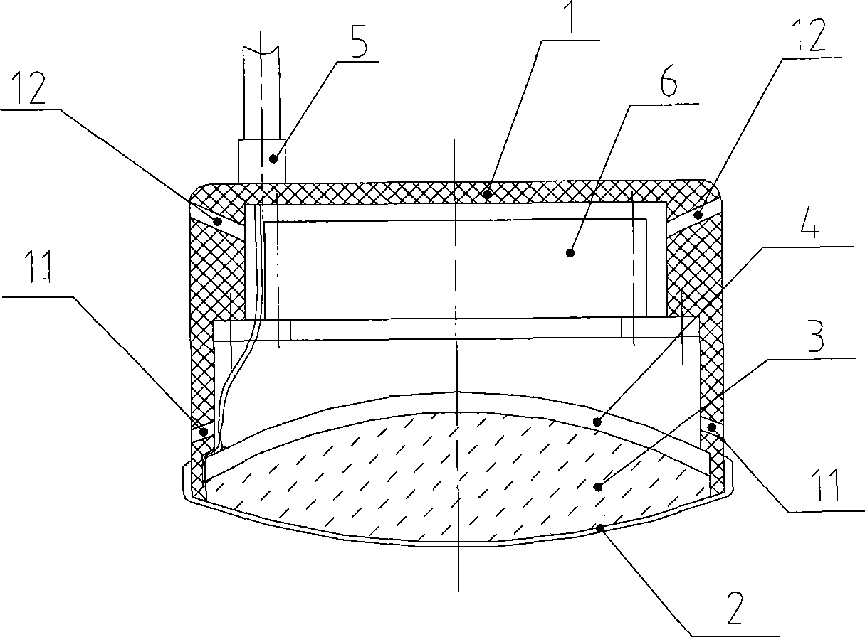
[0032] like figure 2 As shown, in this embodiment, the ultrasonic transducer 4 adopts a spherical shell type ultrasonic transducer. Compared with the planar transducer, the spherical shell transducer can achieve self-focusing of emitted ultrasonic waves.

[0033] The structure of the rest of this embodiment is the same as that of Embodiment 1, and will not be elaborated here.

Embodiment 3

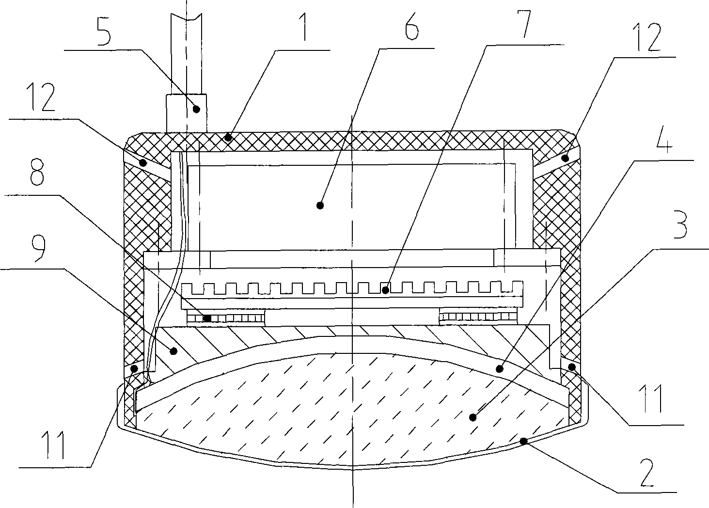
[0035] like image 3 As shown, in the present embodiment, the ultrasonic transducer 4 adopts a spherical shell type ultrasonic transducer; the cooling unit includes a backing 9, a refrigerator 8, a radiator 7 and an axial fan 6 connected in sequence, and the backing 9 is located at On the back of the emitting surface of the ultrasonic transducer 4, its upper and lower surfaces are respectively attached to the surface of the refrigerator 8 and the surface of the spherical shell type ultrasonic transducer 4, and the backing 9 is made of a material with strong thermal conductivity, which is used to place the ultrasonic transducer 4 The heat generated during work is transferred to the refrigerator 8; the refrigerator 8 adopts a semiconductor refrigerator, which is closely attached to the opposite side of the contact surface between the backing 9 and the ultrasonic transducer 4, and realizes cooling of the backing 9; the radiator 7 It is closely attached to the opposite side of the...


PUM


Abstract

The present invention discloses an ultrasonic therapeutic head which comprises a casing (1). An ultrasonic transducer (4) is provided in the casing. One opening is provided on one end of casing (1) and is closed by an energy guiding window (2). The ultrasonic transmitted from the ultrasonic transducer (4) is transmitted to outside through the energy guiding window (2), wherein, an air inlet opening (12) and an air outlet opening (11) are provided on the casing. The cavity between the air inlet opening and the air outlet opening forms a cooling cavity. The heat generated in the operation of ultrasonic transducer (4) is discharged from the air outlet opening (11) after passing through the cooling cavity. The ultrasonic therapeutic head can guarantee the in-time dissipation of heat generated by ultrasonic transducer without using circulating liquid as coolant. The thermal burn of patient generated by the heat that is generated in the operation of ultrasonic transducer can be prevented. Furthermore the normal use of ultrasonic transducer in a long time can be guaranteed.

Description

technical field [0001] The invention belongs to the technical field of ultrasonic treatment, and in particular relates to an ultrasonic treatment head. Background technique [0002] In the field of traditional ultrasonic therapy technology, the ultrasonic transducer in the treatment head will generate a lot of heat during use. If the heat is not dissipated in time, it may cause burns to the patient and affect the treatment head. is the lifetime of the ultrasonic transducer. [0003] In general, in order to avoid the temperature of the treatment head from being too high, the ultrasonic transducer usually has to be used under the condition of reduced power, or it can be used continuously for a period of time, and then continue to be used after it cools down. In order to solve the above problems, the usual practice is to equip the treatment head with a water circulation cooling device, such as the ultrasonic treatment device in the Chinese patent (patent number: ZL 01144259.X)...

Claims


Application Information

Patent Timeline
Patent Type & Authority Applications(China)
IPC IPC(8): A61N7/00A61N7/02
CPCA61B2018/00023A61B8/4281A61N7/00G10K11/004
Inventor 胡弟元敬李毛爱华赵纯亮
Owner RONGHAI SUPERSONIC MEDICINE EN
Why Eureka
Try Eureka