Sputtering apparatus

A sputtering equipment and equipment technology, applied in the directions of sputtering plating, ion implantation plating, coating, etc., can solve the problem that the inflow or outflow of sputtered particles cannot be prevented, and achieve the effect of preventing mutual contamination

Active Publication Date: 2009-07-01
CANON ANELVA CORP
View PDF2 Cites 22 Cited by
  • Summary
  • Abstract
  • Description
  • Claims
  • Application Information

AI Technical Summary

Problems solved by technology

[0010] However, none of the above-referenced baffle mechanisms prevents the inflow or outflow of sputtered particles from a target disposed in a vacuum chamber that processes a substrate

Method used


Image

  • Sputtering apparatus
  • Sputtering apparatus
  • Sputtering apparatus

Examples


Embodiment Construction

[0021] Preferred embodiments of the present invention will be described below with reference to the accompanying drawings.

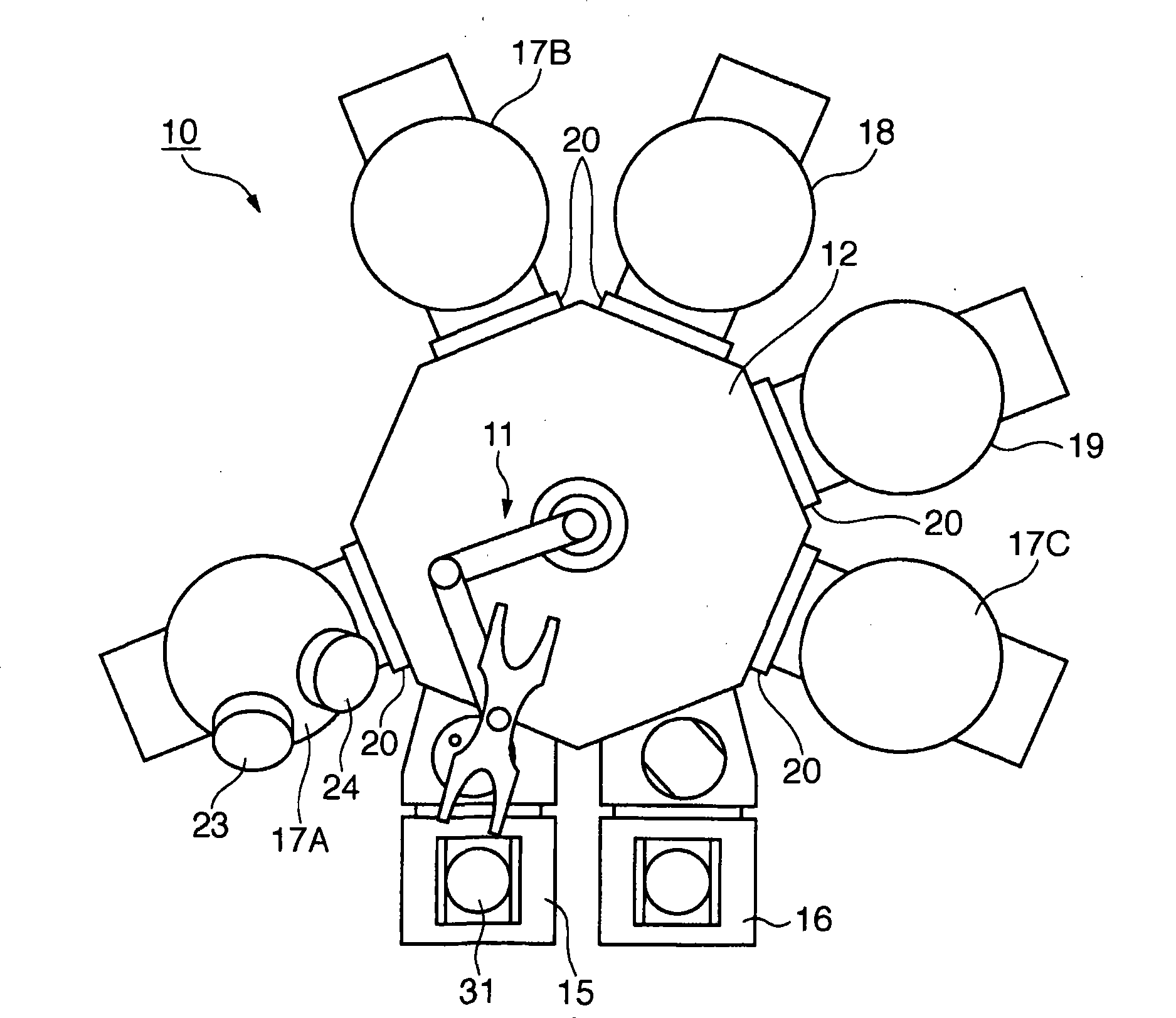
[0022] will refer to figure 1 The sputtering apparatus according to the present embodiment is explained. For example, the sputtering apparatus is an apparatus for manufacturing an optical multilayer interference filter. It should be noted that the sputtering device is not limited to devices having this arrangement. figure 1 A schematic arrangement of the internal mechanism of the sputtering apparatus is shown. In the following description, "apparatus for manufacturing an optical multilayer film interference filter" will also be referred to as "optical multilayer film manufacturing sputtering apparatus" (or simply "sputtering apparatus"). The optical multilayer film manufacturing sputtering apparatus 10 has a cluster arrangement and includes a plurality of vacuum chambers. Some of the vacuum chambers among the plurality of vacuum chambers are film-f...


PUM

PropertyMeasurementUnit
distanceaaaaaaaaaa
sizeaaaaaaaaaa

Abstract

A sputtering apparatus to form a film on a substrate includes an electrode arranged in a vacuum chamber and having a placing surface to place a target on it, a stationary portion provided on the peripheral portion of the placing surface, a shutter mechanism to shield in the vacuum chamber the target placed on the placing surface, and a moving mechanism which sets in the vacuum chamber the shutter mechanism at a predetermined position. Of the stationary portion and the movable portion of the shutter mechanism, one is provided with a recess and the other one is provided with a projection. When the moving mechanism sets the shutter mechanism at a position close to the stationary portion, the projection is inserted in the recess.

Description

technical field [0001] The present invention relates to a sputtering apparatus, and more particularly to a sputtering apparatus having a shutter mechanism adapted to prevent scattering of sputtered particles from a target arranged in a vacuum chamber for processing a substrate, Or prevent sputtered particles from flowing out from another target. Background technique [0002] Among the sputtering apparatuses, there is known a sputtering apparatus in which a plurality of targets made of different target materials are set in a vacuum chamber which processes a substrate by, for example, film formation. In this sputtering apparatus, a target is selected according to the type of film to be formed on a substrate, and the selected target is sputtered. In this manner, a desired multilayer film is formed on a substrate disposed in a vacuum chamber. [0003] Each target is disposed on a placement surface that is disposed to a corresponding electrode for disposing the target on the pl...

Claims


Application Information

Patent Timeline
Patent Type & Authority Applications(China)
IPC IPC(8): C23C14/34
CPCH01J37/3447C23C14/568H01J37/34C23C14/3407
Inventor 小林幸弘吉塚浩一太田俊之
Owner CANON ANELVA CORP
Why Eureka
Try Eureka