Circulating hydraulic electrogenerating and energy storage apparatus

An energy storage device and circulation technology, which is applied in the field of circulation hydroelectric power generation and energy storage devices, can solve the problems of difficult power source acquisition and inability to be reused

Inactive Publication Date: 2009-07-01
陈守雄
View PDF0 Cites 7 Cited by
  • Summary
  • Abstract
  • Description
  • Claims
  • Application Information

AI Technical Summary

Problems solved by technology

[0006] The main purpose of the present invention is to overcome the deficiencies and defects of the prior art, and propose a circulating hydroelectric power generation and energy storage device, the top and bottom of the carrier are respectively provided with a water supply tank and a water storage tank, and the carrier is provided with a continuously curved drainage The channel and the drainage channel are respectively connected with the drain pipe of the water supply tank and the water inlet pipe of the water storage tank, and the inner hub of the water storage tank is equipped with a water wheel, and the water wheel is linked with a pump, and the water pump is connected to the water inlet pipe of the water supply tank. It can solve the problem that the power source of the existing power generation device is difficult to obtain and cannot be reused, and achieve the practical progress of recyclable power generation water

Method used


Image

  • Circulating hydraulic electrogenerating and energy storage apparatus
  • Circulating hydraulic electrogenerating and energy storage apparatus
  • Circulating hydraulic electrogenerating and energy storage apparatus

Examples


Embodiment Construction

[0038] In order to achieve the above purpose and effects, the technical means and structures adopted by the present invention are described in detail in conjunction with the accompanying drawings for the preferred embodiments of the present invention. The features and functions are as follows for a complete understanding.

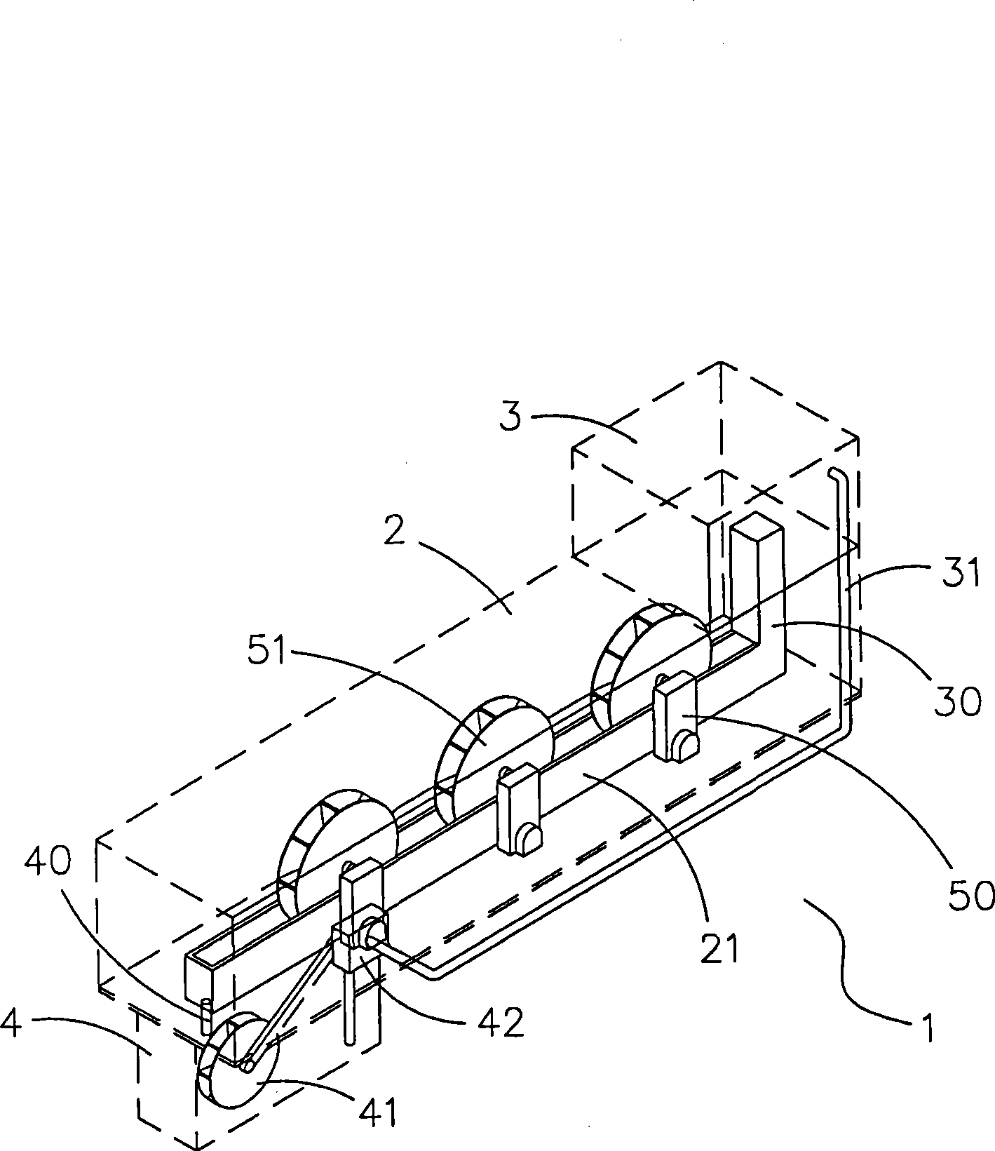
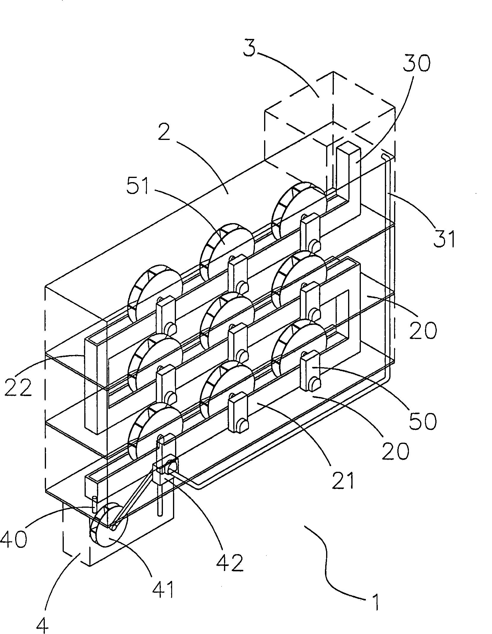
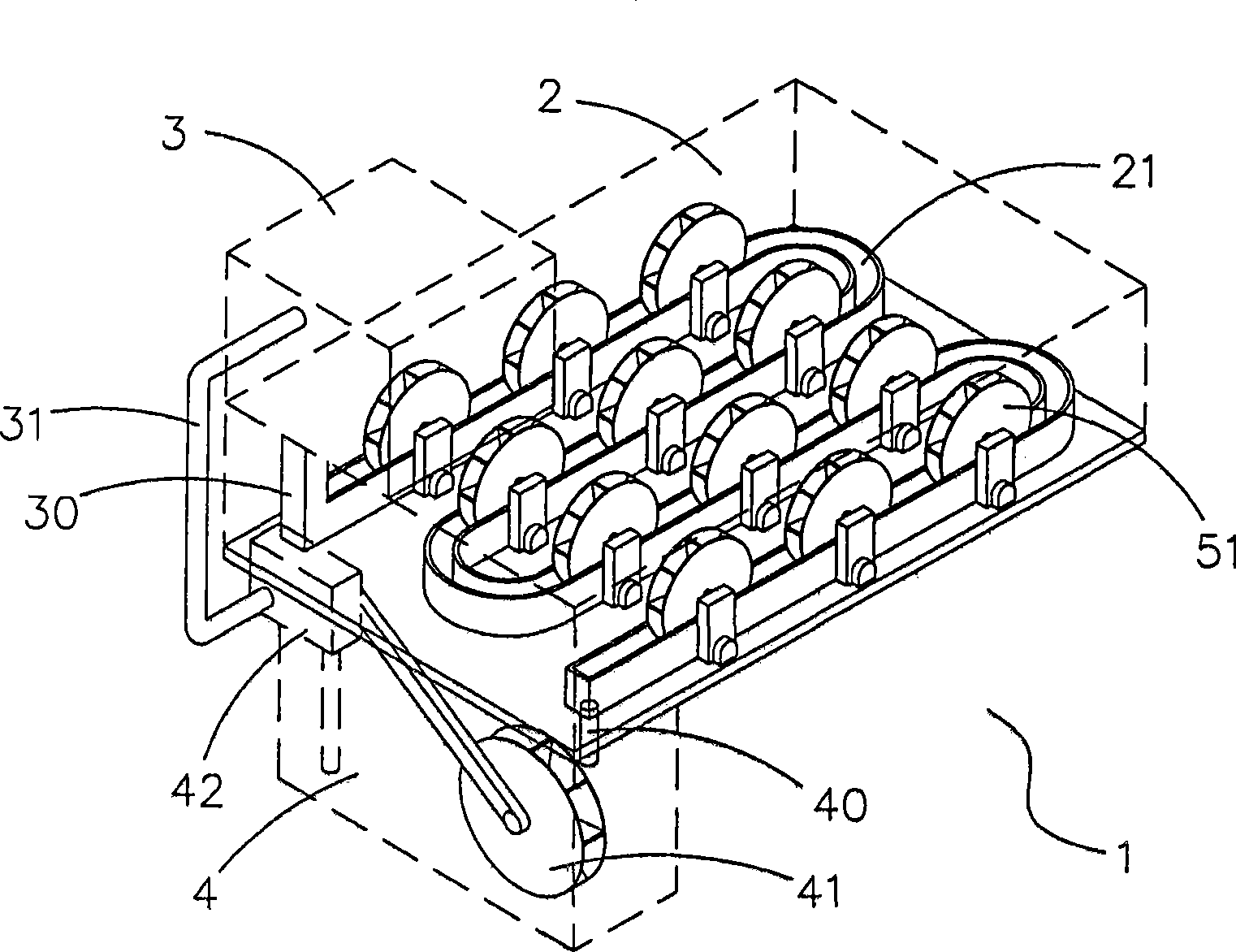
[0039] see figure 1 Shown is a perspective view of a preferred embodiment of the present invention Figure 1 , it can be clearly seen from the figure that the circulating hydroelectric power generation and energy storage device 1 of the present invention includes a carrier 2, a water supply tank 3, a water storage tank 4 and a hydroelectric generating set 50, wherein:

[0040] The interior of the carrier 2 is hollow, and a drainage channel 21 is provided at the bottom, and the carrier 2 can be one of an apartment, a mansion, a building, a concrete building or a reinforced concrete building.

[0041] The water supply tank 3 contains fluids such as water, an...


PUM


Abstract

The present invention relates to a cycle hydroenergy production and energy storage apparatus, which comprises a carrier, the top of the carrier is provided with a water supply groove, and the bottom is provided with a water storage groove; the carrier is provided with a water drainage passage inside; the water drainage passage connects with the water supply groove and the water storage groove respectively; the water storage groove is provided with a water wheel inside; the water wheel interlocks a water pump; the water pump is connected to the water supply groove; and the electricity generator of the hydroenergy production group is mounted around the water drainage passage, the bottom of the water wheel set on the electricity generator is contained in the water drainage passage, thereby, water impels the water wheel to make the electricity generator generate electric power through water drainage passage, after that, water impacts the water wheel to have the water pump drain it to the water supply groove, so as to realize practical progress of water in cycle power generation.

Description

technical field [0001] The invention relates to a hydroelectric power generation and energy storage device, in particular to a circulating hydroelectric power generation and energy storage device which can circulate water for power generation and has energy storage at the same time. Background technique [0002] Common small power generation devices mostly use fuel such as gasoline or diesel as the power source. The purpose is to drive the generator to generate electricity through the combustion of fuel. [0003] Using fuel oil as the power source for power generation can generate a large amount of electric energy in a short period of time, but after burning fuel oil, it is easy to generate exhaust gas and easily cause air pollution. At the same time, as the production capacity of crude oil decreases, the cost of fuel oil also increases. When using said generating device, must bear huge fuel expense. [0004] Furthermore, although small-scale wind power generation devices o...

Claims


Application Information

Patent Timeline
Patent Type & Authority Applications(China)
IPC IPC(8): F03B13/06F03B13/08F03B13/00F03D9/00F02B63/04F01D15/10F03G6/00H02K7/18F04D13/06F16M3/00
CPCY02E10/22Y02E10/725Y02E60/17Y02E10/20Y02E60/16Y02P80/10
Inventor 陈守雄
Owner 陈守雄
Why Eureka
Try Eureka