Method and device for monitoring differential signal fault
A differential signal and fault monitoring technology, which is applied in the direction of measuring devices, line transmission monitoring/testing, measuring electricity, etc., can solve the problems of long fault location time, lower transmission efficiency, and inability to accurately locate replaceable units, etc., to achieve low cost, Enhanced sensitivity and simple structure
- Summary
- Abstract
- Description
- Claims
- Application Information
AI Technical Summary
Problems solved by technology
Method used
Image

Examples
Embodiment Construction
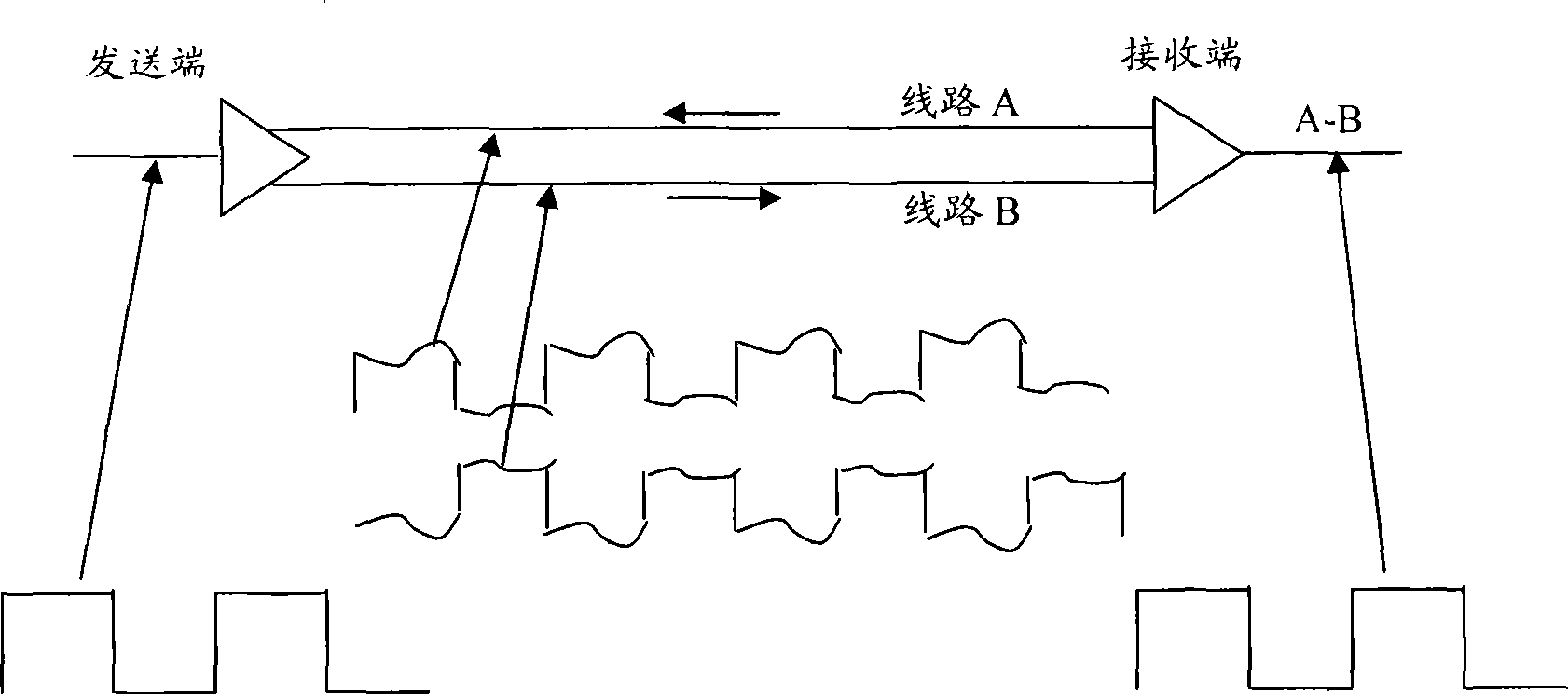
[0024] Differential Signal (DS) transmission technology refers to a communication transmission technology that uses a pair of physical lines with opposite current directions and equal magnitudes to transmit signals. Such as figure 2 As shown, the sending end converts the signal to be sent into two signals with opposite voltages and the same amplitude, and transmits the signals through line A and line B respectively; the signal received by the receiving end is the difference between the two signals. The impact of external electromagnetic interference on the line is usually to change the voltage amplitude of line A and line B at the same time. In this case, the signal difference between line A and line B will basically not change, so the differential signal is basically not affected by external interference. And because the currents of line A and line B are opposite and the amplitudes are equal, the electromagnetic fields radiated to the outside are all canceled out, and the el...
PUM
 Abstract
Description
Claims
Application Information
 - R&D
- Intellectual Property
- Life Sciences
- Materials
- Tech Scout
- Unparalleled Data Quality
- Higher Quality Content
- 60% Fewer Hallucinations
Browse by: Latest US Patents, China's latest patents, Technical Efficacy Thesaurus, Application Domain, Technology Topic, Popular Technical Reports.
© 2025 PatSnap. All rights reserved.Legal|Privacy policy|Modern Slavery Act Transparency Statement|Sitemap|About US| Contact US: help@patsnap.com