Dust condensing passage, charging draft member, frictional charging resin pipe, electric vacuum cleaner
A technology of friction electrification and dust, applied in the direction of suction filter, external electrostatic separator, pipe, etc., can solve the problems of particle accumulation, larger occupied area, complex structure, etc., to increase the quality and eliminate the reduction of dust suction force (power) Effect
- Summary
- Abstract
- Description
- Claims
- Application Information
AI Technical Summary
Problems solved by technology
Method used
Image
Examples
Embodiment approach 1-1-1
[0320] Figure 10 It is a figure which shows the whole electric vacuum cleaner provided with the dust aggregation passage of this invention as Embodiment 1-1-1 of this invention.
[0321] like Figure 10 As shown, the electric vacuum cleaner 6b is equipped with the extension pipe 502, the suction hose 504, and the connection part 505 as a flow path. The extension pipe 502, the suction hose 504, and the connection part 505 are sequentially connected. The electric vacuum cleaner 6b is provided with a frictional electrification path 161 having a length b at the downstream side of a distance c from the upstream end of the extension pipe 502 having a length a, and a connection portion 505 having a length d at the downstream side thereof. The collision-facilitating path 162 of . In the frictional electrification path 161, the first frictional electrification part for positively electrifying the dust and the second triboelectric electrification part for negatively electrifying the...
Embodiment approach 1-1-2
[0340] Figure 11 It is the figure which shows the whole electric vacuum cleaner equipped with the dust aggregation path of this invention as embodiment 1-1-2 of this invention, Figure 12 It is explanatory drawing of the structure of the main body of the electric vacuum cleaner of this invention.
[0341] Embodiment 1-1-2 differs from Embodiment 1-1-1 in that a friction electrification path is disposed inside the connecting pipe. The other parts of Embodiment 1-1-2 are the same as Embodiment 1-1-1.
[0342] like Figure 11 and Figure 12 As shown, in the electric vacuum cleaner 500, the suction port 501 is sequentially connected to the thin side 511 of the extension pipe, the thick side 512 of the extension pipe, the connecting pipe 503 with the handle 503a, and the freely bending suction hose 504, and connected to the The cleaner body 506 is connected. The vacuum cleaner main body 506 accommodates an electric blower 567, a dust collection unit 561, a dust collection box...
Embodiment approach 1-1
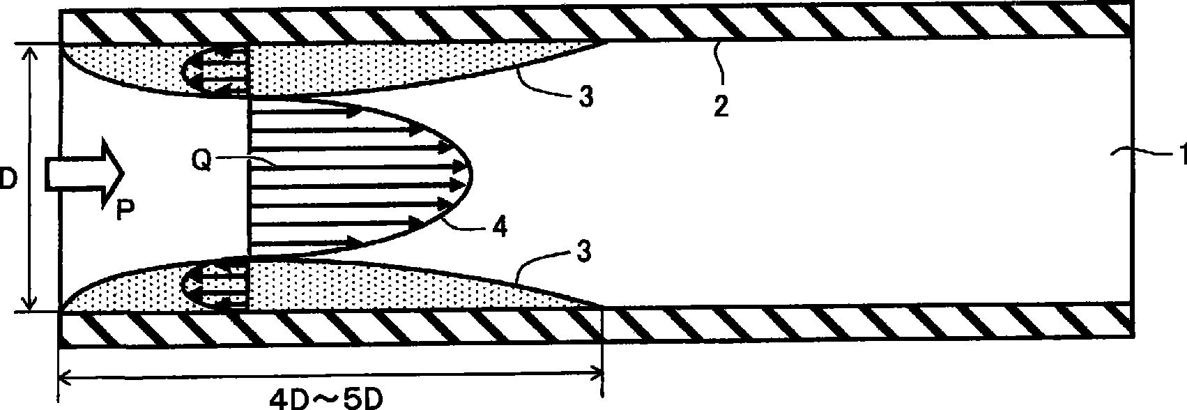
[0358] When the dust to be condensed is composed of a specific substance, it is a dust collecting device that sucks and collects the dust composed of a specific substance. It has: a suction port that sucks the dust and air together, and rides the dust on the air. The flow of the flow is the path through which the airflow is conveyed to the downstream side, the drive source communicating with the path to generate the airflow, the dust collection part arranged in the path to separate the air and dust and leave the dust, and the air separated from the dust to be discharged to the outside In the dust collecting device of the blowing outlet, a dust aggregation path for agglomerating dust is arranged on the upstream side of the dust collection part in the path, the upstream part of the dust aggregation path constitutes a frictional electrification path, and the downstream part constitutes a collision promotion path.
[0359] Moreover, the frictional electrification path as the upstre...
PUM
| Property | Measurement | Unit |
|---|---|---|
| Tube chief | aaaaa | aaaaa |
| The inside diameter of | aaaaa | aaaaa |
| Resistivity | aaaaa | aaaaa |
Abstract
Description
Claims
Application Information
 - R&D
- Intellectual Property
- Life Sciences
- Materials
- Tech Scout
- Unparalleled Data Quality
- Higher Quality Content
- 60% Fewer Hallucinations
Browse by: Latest US Patents, China's latest patents, Technical Efficacy Thesaurus, Application Domain, Technology Topic, Popular Technical Reports.
© 2025 PatSnap. All rights reserved.Legal|Privacy policy|Modern Slavery Act Transparency Statement|Sitemap|About US| Contact US: help@patsnap.com


