
Mold flux and continuous casting method using the same

A technology of mold slag and continuous casting, which is applied to casting equipment, casting melt containers, and control of molten metal pouring from casting ladles. Quality, suppression of surface cracks, control of heat transfer effects

Inactive Publication Date: 2009-07-01
POHANG IRON & STEEL CO LTD
View PDF0 Cites 13 Cited by
  • Summary
  • Abstract
  • Description
  • Claims
  • Application Information

AI Technical Summary

Problems solved by technology

However, more mold flux is mixed into the molten steel, and the average amount of heat transferred decreases
As a result, lead to breakout

Method used


Image

  • Mold flux and continuous casting method using the same
  • Mold flux and continuous casting method using the same
  • Mold flux and continuous casting method using the same

Examples


Embodiment Construction

[0032] Hereinafter, embodiments of the present invention will be described in detail with reference to the accompanying drawings. However, the present invention is not limited to the following examples. In addition, the present invention can be implemented in many different forms and should not be construed as being limited to the embodiments presented here. Rather, these embodiments are provided so that this disclosure will be thorough and complete, and will fully convey the concept of the present invention to those skilled in the art. In the drawings, the same reference numerals denote the same elements.

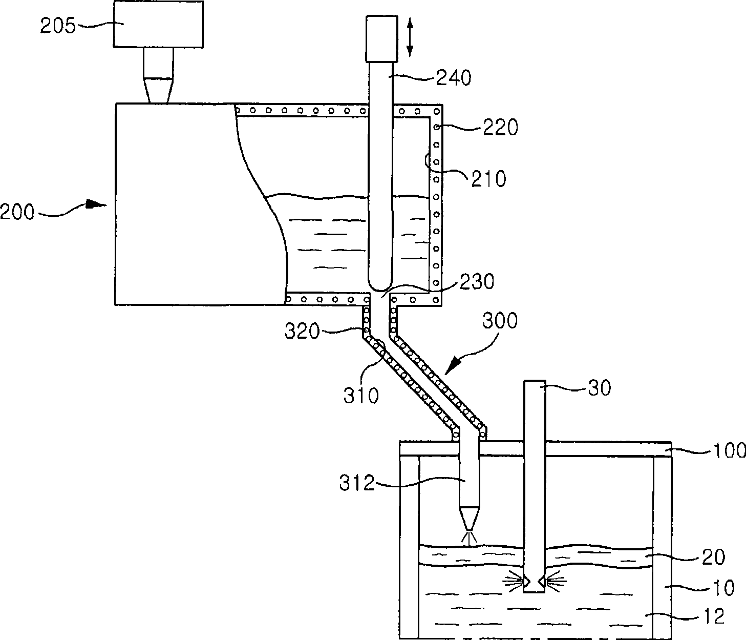
[0033] image 3 It is a diagram showing a schematic structure of a continuous casting machine using molten mold flux.

[0034] Reference image 3 , The continuous casting machine includes: a mold 10; an immersion nozzle 30 for supplying molten steel to the mold 10; a mold cover 100 for covering the upper part of the mold 10; a mold slag melting unit 200 for melting Mold powde...


PUM

PropertyMeasurementUnit
Thermal conductivityaaaaaaaaaa
Absorption coefficientaaaaaaaaaa

Abstract

A mold flux including 20 to 50 wt% of CaO, 20 to 50 wt% of SiO2, 20 wt% or less of Al2O3, 20 wt% or less of Na2O, 10 wt% or less of Li2O, 20 wt% or less of B2O3, and 10 wt% or less of MgO, and a continuous casting method using the mold flux. The quality of products can be improved, since the occurrence of surface cracks of cast pieces is suppressed. Further, since the occurrence of break-out is prevented, it is possible to improve the process stability.

Description

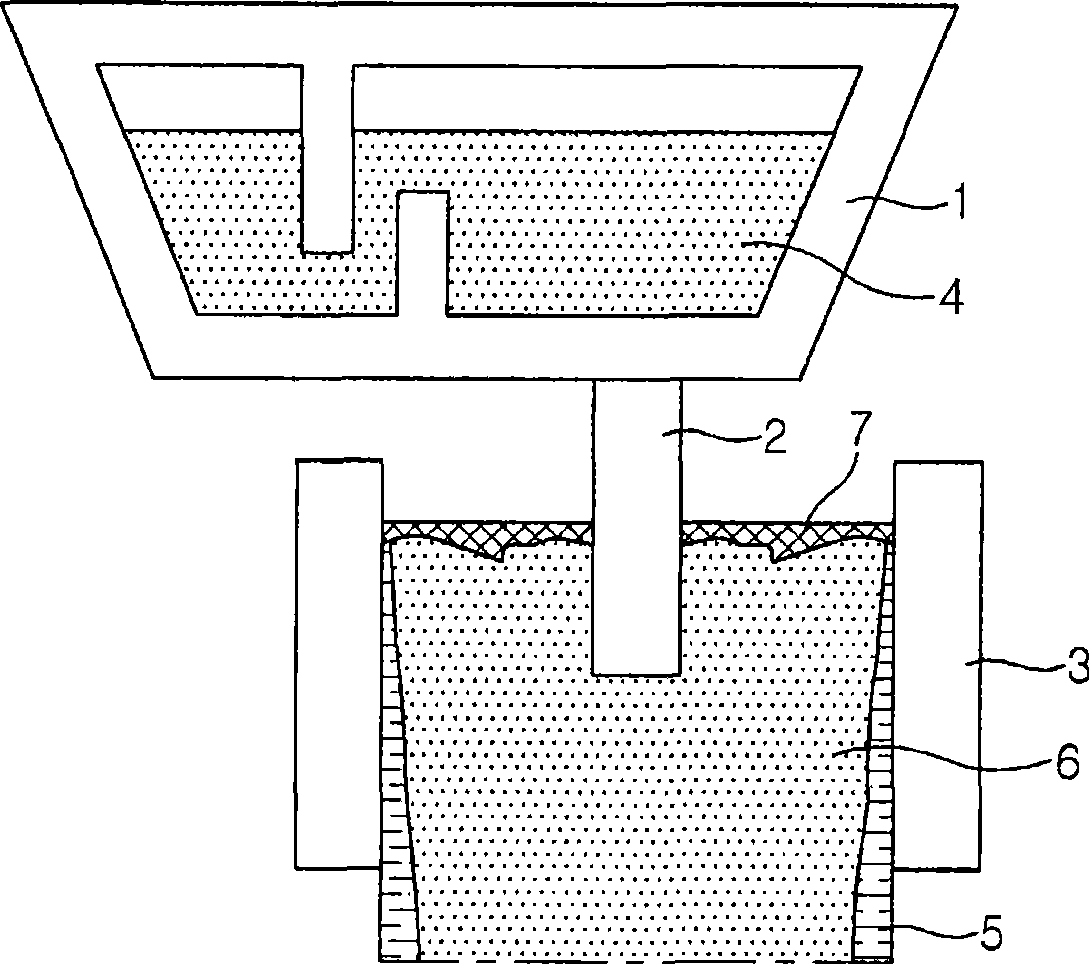
Technical field [0001] The present invention relates to a mold flux and a continuous casting method using the mold flux, and more specifically, to a continuous casting method using molten mold flux. Background technique [0002] In a general steelmaking method, the pretreatment process of molten iron, the converter refining process, the secondary refining process, and the continuous casting process are sequentially performed. [0003] Such as figure 1 As shown, in order to manufacture castings (i.e. general terms for slabs, billets, blooms, shaped billets, etc.) through a continuous casting process, molten steel is supplied from a ladle, and then the molten steel passes through the tundish for storing molten steel 1, an immersion nozzle 2 and crystallizer 3. Then, the molten steel is cooled in the mold 3 by the cooling effect of the mold 3, and a solidified shell 5 is formed. The solidified shell 5 formed by cooling molten steel is guided by a guide roller provided below the mol...

Claims


Application Information

Patent Timeline
IPC IPC(8): B22D11/108
CPCB22D11/108B22D11/16B22D37/00B22D41/005B22D41/50
Inventor 赵重郁郑玹锡金句和朴重吉李相浩文己显
Owner POHANG IRON & STEEL CO LTD
Learn More