
Composite cooling structure for turbine stator blade of gas turbine

A gas turbine and composite cooling technology, applied in mechanical equipment, engine components, machines/engines, etc., can solve problems such as poor temperature uniformity of blades, difficulties in mold design and manufacturing, and reduced service life of stationary blades, so as to improve overall temperature uniformity , Reduce manufacturing difficulty and cost, increase the effect of service life

Pending Publication Date: 2022-04-19
HANGZHOU TURBINE POWER GRP
View PDF2 Cites 0 Cited by
  • Summary
  • Abstract
  • Description
  • Claims
  • Application Information

AI Technical Summary

Problems solved by technology

[0006] First, the structure design of the diversion tube is complex and difficult to manufacture
Because the shape of the guide tube is generally consistent with the shape of the inner cavity of the stator blade, it is an irregular three-dimensional curved surface, and it is formed by stamping. Die design and manufacture are relatively difficult, resulting in low processing yield and high cost
[0007] Second, the thermal stress concentration at the trailing edge of the stator blade
The cooling air at the trailing edge of the stationary blade comes from the outlet of the compressor. Compared with the gas temperature, the temperature is very low. It enters the trailing edge chamber and flows out from the slit after passing through the convective heat exchange between the trailing edge pillars and ribs. Temperature, the temperature uniformity of the entire blade is poor, resulting in the concentration of thermal stress on the trailing edge of the stator blade, making the trailing edge of the stator blade a failure concentration point of the stator blade, reducing the service life of the stator blade

Method used


Image

  • Composite cooling structure for turbine stator blade of gas turbine
  • Composite cooling structure for turbine stator blade of gas turbine
  • Composite cooling structure for turbine stator blade of gas turbine

Examples


Embodiment 1

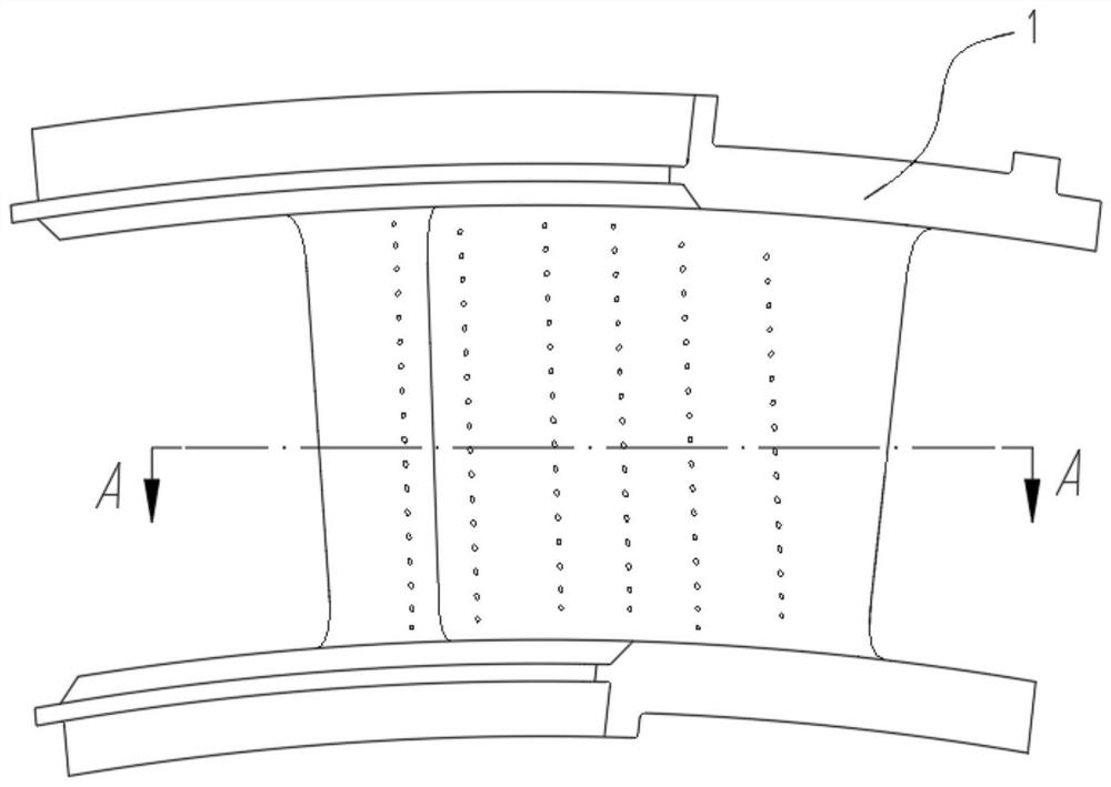
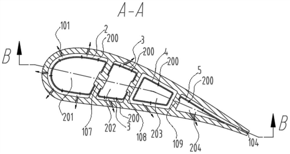
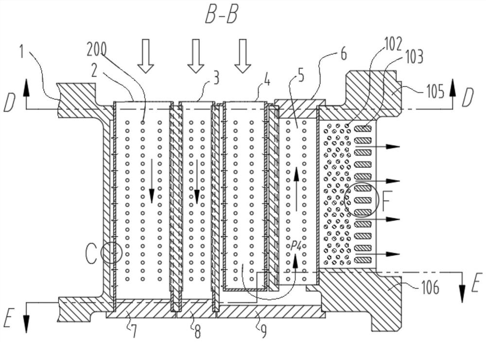
[0043] like Figure 1-6 As shown, the present invention provides a composite cooling structure for gas turbine stator blades, including a stator blade 1, the stator blade 1 is a hollow cooling blade, the upper end of the stator blade 1 has an upper edge plate 105, and the lower end has a lower edge plate 106. Multiple exhaust membrane holes 101 are set on the side wall; the first partition 107, the second partition 108 and the third partition 109 are arranged inside the stator blade 1, and the first partition 107 is formed between the front edge of the stator blade 1 and the first partition 107. A cavity 201, a second cavity 202 is formed between the first partition 107 and the second partition 108, a third cavity 203 is formed between the second partition 108 and the third partition 109, the third partition 109 A fourth inner cavity 204 is formed between the tail edge and the first inner cavity 201. A first blocking cover 7 is arranged below the first inner cavity 201, and a ...

Embodiment 2

[0054] Please refer to Figure 8 As shown, the difference between this embodiment and Embodiment 1 is that no protrusion is provided in the middle of the first partition 107, and four grooves are provided at both ends of the first partition 107, including two grooves in the first inner cavity 201. a groove, and two grooves in the second inner chamber 202, the cross section of the first ferrule 2 is U-shaped, and the two sides of the first ferrule 2 are inserted into the grooves on the first partition 107 for Positioning; the middle part of the second dividing plate 108 is not provided with protrusions, and the two ends of the second dividing plate 108 are provided with four grooves, including two grooves in the second inner cavity 202 and two grooves in the third inner cavity 203. two grooves, the second ferrule 3 is a straight sheet or a circular arc sheet with a certain radian, one end side of the two second ferrule 3 is inserted into the groove of the first partition 107, t...


PUM


Abstract

The invention relates to a gas turbine stator blade cooling system, in particular to a gas turbine stator blade composite cooling structure which comprises a stator blade, and four hollow inner cavities are formed in the stator blade. The hollow inner cavity close to the front edge of the stator blade is a first inner cavity, the hollow inner cavity close to the tail edge of the stator blade is a fourth inner cavity, a first insertion core is arranged in the first inner cavity, and a fourth insertion core is arranged in the fourth inner cavity; the first insertion core is of a thin-wall annular structure with two open ends, and the cross section of the first insertion core is of an open structure; a radial distance is reserved between the first insertion core and the inner wall of the stationary blade; a plurality of air holes are formed in the surface of the insertion core; a plurality of rows of air film holes are formed in the side wall of the static blade. The insertion core is processed and manufactured by adopting a mature stamping process, so that the manufacturing difficulty and the processing cost are reduced; and meanwhile, the overall temperature uniformity of the blade is improved, thermal stress is reduced, the failure probability of the tail edge of the stator blade is reduced, and the service life of the blade is prolonged.

Description

technical field [0001] The invention relates to a cooling system for a gas turbine stator blade, in particular to a composite cooling structure for a gas turbine turbine stator blade. Background technique [0002] From the simple cycle of the gas turbine, it can be seen that the specific power and performance of the gas turbine can be improved by increasing the initial gas temperature at the turbine inlet. The temperature around the turbine stator blades is high and the environment is harsh. The initial gas temperature of the F-class gas turbine is about 1400°C, which has far exceeded the tolerance limit of the metal of the stator blades. Therefore, the advanced cooling structure design of turbine stator blades is very important for the safe operation of gas turbines. [0003] At present, the turbine stator blades of gas turbines generally adopt a hollow structure, and cooling air is passed through the interior to take away the heat of the stator blades. The more common co...

Claims


Application Information

Patent Timeline
Patent Type & Authority Applications(China)
IPC IPC(8): F01D9/02F01D25/12
CPCF01D9/02F01D25/12
Inventor 初鹏邵文洋姚世传吴宏超谷庭伟谢健隋永枫蓝吉兵李冬青薛临风邵艳红
Owner HANGZHOU TURBINE POWER GRP
Learn More