Drive with an energy recovery function having a brake pressure control valve

A technology of energy recovery and drive, applied in the direction of brakes, brake types, hydrostatic brakes, etc., can solve the problems of no longer storing pressure energy, structural complexity, unknown throttling function throttle unit, etc., to increase flow resistance , the effect of a low level of circuit complexity

Inactive Publication Date: 2009-07-01
HYDROMATIK GMBH
View PDF1 Cites 6 Cited by
  • Summary
  • Abstract
  • Description
  • Claims
  • Application Information

AI Technical Summary

Problems solved by technology

[0003] The system proposed therein has the disadvantage that the transfer from the accumulator to the additional closed circuit is performed when the storage element has reached the limit of its capacity and thus can no longer be used to store pressure energy when performing a braking operation
However, it is unknown from US 6,712,166 B2 to provide a throttle unit that allows

Method used


Image

  • Drive with an energy recovery function having a brake pressure control valve
  • Drive with an energy recovery function having a brake pressure control valve

Examples


Embodiment Construction

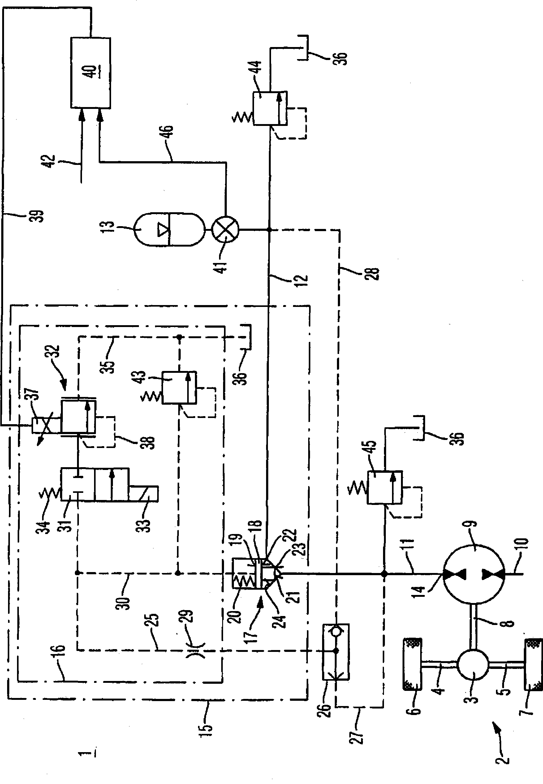
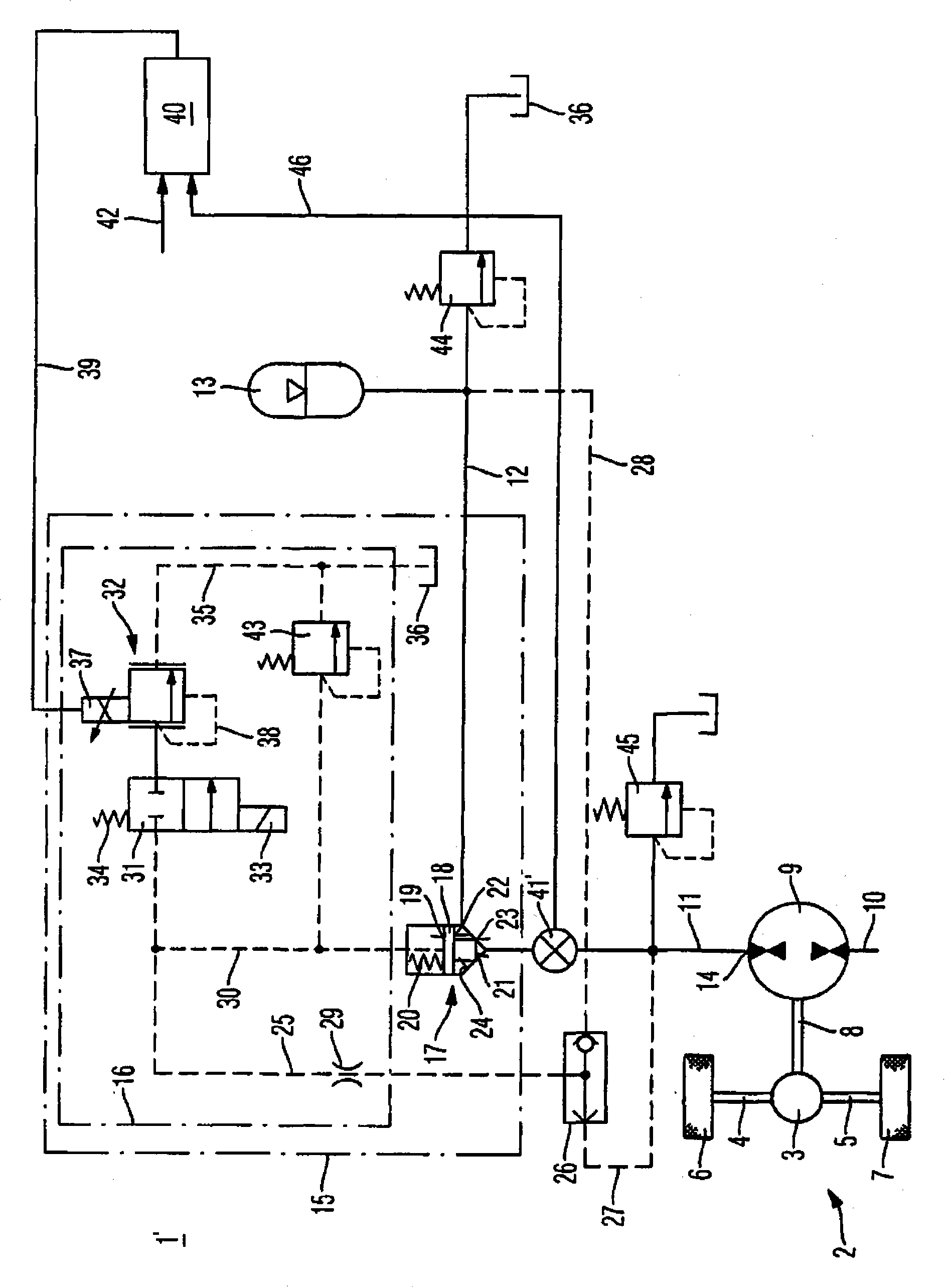
[0017] figure 1 is the hydraulic circuit diagram of the first embodiment of the driver 1 with energy recovery function. In the exemplary embodiment shown, the drive 1 is provided for energy recovery, for example in a travel drive 2 of a refuse collection vehicle or a fork-lift truck. These vehicles have intensive travel cycles, that is to say braking and acceleration operations often follow each other closely.

[0018] The travel drive 2 comprises a differential 3 which acts via a first half shaft 4 and a second half shaft 5 on a first driven wheel 6 and a second driven wheel 7 . The differential 3 is connected to a hydrostatic piston engine 9 via an output shaft 8 . For reasons of clarity, further components belonging to the travel drive 2 are not shown in the figure. The hydrostatic piston engine 9 can be a separate piston engine fully used for energy recovery or a hydraulic motor of the hydrostatic travel drive. The connection to the differential 3 of the travel drive 2...


PUM


Abstract

The invention relates to a drive (1) having an energy recovery function. The drive having an energy recovery function comprises a hydrostatic piston machine (9) and at least one storage element (13) which is connected to said hydrostatic piston machine. Said hydrostatic piston machine (9) and the at least one storage element (13) are connected together by means of a storage line. Said storage line is divided into a first storage line section (11) and into a second storage line section (12) by a throttle value unit (15). Said throttle valve unit (15) comprises a control pressure valve unit (16) and a built-in valve (17). The control pressure valve unit (16) produces a control pressure which acts upon the built-in valve (17).

Description

technical field [0001] The invention relates to a driver with energy recovery function. Background technique [0002] A drive with energy recovery is known from US 6,712,166 B2. In the system proposed therein, pressure medium is conveyed by the pump / motor arrangement on the one hand from the reservoir into the pressure accumulator as long as the pump / motor arrangement is driven by the mass inertia of the vehicle during deceleration operation. In order to subsequently also allow the vehicle to be braked by the hydrostatic drive, when the capacity limit of the pressure accumulator is reached, it is proposed in the drive proposed therein that a flow resistance is generated by bypassing the storage element and that the pump / motor arrangement closes the circuit Transmission of pressure medium. [0003] The system proposed therein has the disadvantage that the transfer from the accumulator to the additional closed circuit is performed when the storage element has reached the lim...

Claims


Application Information

Patent Timeline
IPC IPC(8): B60T10/04B60T1/10
CPCB60K6/12B60T1/093B60T10/04Y02T10/92Y02T10/6208B60T1/10Y02T10/62
Inventor 马蒂亚斯·米勒乔治·劳施
Owner HYDROMATIK GMBH
Why Eureka
Try Eureka