Tracheal cannula

A technique for tracheal intubation and airway tube, which is applied in the direction of tracheal intubation, etc., can solve the problems of difficulty in ventilation of both lung lobes and intubation, and achieves the effects of simple structure, convenient operation and reasonable structure.

Inactive Publication Date: 2009-07-08
张晓明
View PDF0 Cites 14 Cited by
  • Summary
  • Abstract
  • Description
  • Claims
  • Application Information

AI Technical Summary

Problems solved by technology

[0003] The main purpose of the present invention is to develop a tracheal intubation to solve the technical problems of difficulty in intubation and difficulty in ventilating both lung lobes in the prior art

Method used


Image

  • Tracheal cannula
  • Tracheal cannula
  • Tracheal cannula

Examples


Embodiment 1

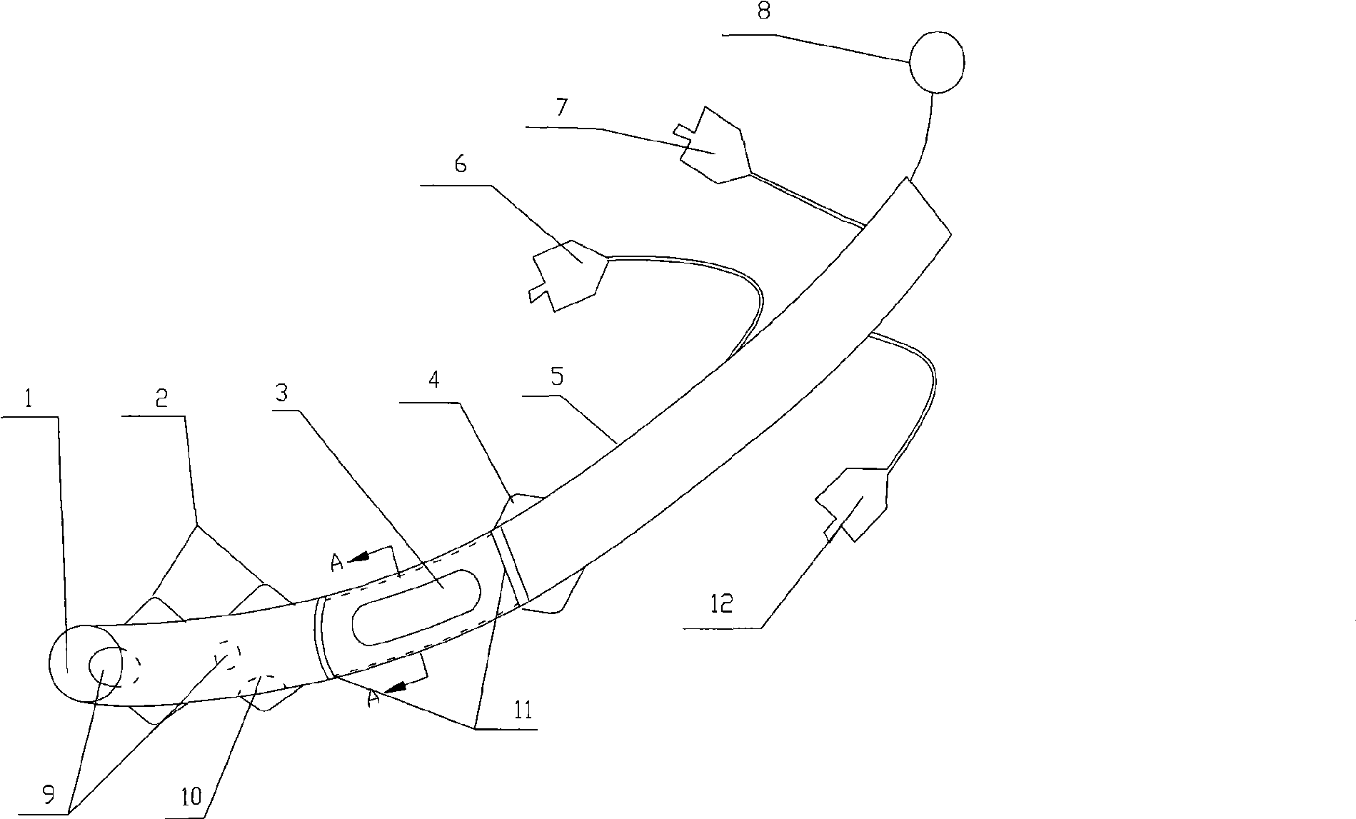
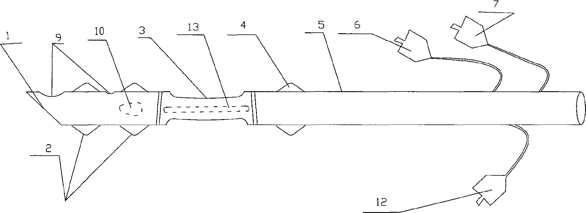
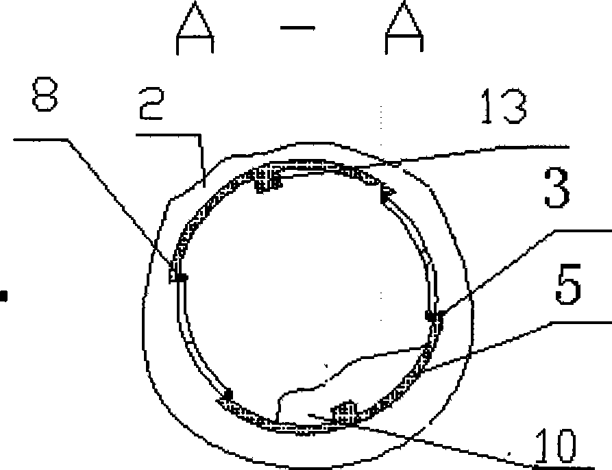
[0029] Embodiment 1: A kind of endotracheal intubation, the front end of the intubation is provided with two overcoats, that is, the conjoined cuff 2 and the second overcoat 4, and each overcoat has a thin airway connected to the outside of the endotracheal tube. On the injection interface, the endotracheal intubation tube also has an inner tube 16, one end of the inner tube 16 is provided with a machine interface end 17; the outer tube 5 is longer than the inner tube 16, and the socket end of the outer tube is a slope 1, and the outer bag is arranged on the outer tube. On the outer wall, an inner cuff 10 is also arranged on the inner wall of the outer tube apart from the socket end, and the injection port 12 of the inner cuff 10 is arranged at the other end of the outer tube; The length of the long waist-shaped air holes 3 on both sides is shorter than the distance between the two outer bags 2 and 4. With such an arrangement of inner and outer tubes, when the inner tube block...

Embodiment 2

[0030] Embodiment 2: Embodiment 2 is the superposition type of inner and outer tubes as in Embodiment 1. The difference is that a clamp 14 is provided on the socket port of the inner tube 16; two clamping grooves 11 are provided on the inner side of the outer tube, and the dimensions of the two clamping grooves are Compatible with the clamp, the distance between the two clamping grooves 11 is the twitch stroke of the inner tube. Two axially long clamps 13 are also arranged on the inner wall of the outer tube where the long waist-shaped air holes 3 are vertical, and two long clamping grooves 15 are formed on the outer side of the inner tube correspondingly. This design is to ensure that the inner tube can be smoothly pumped and in place in the outer tube. Because two long waist-shaped air holes 3 are opened, the outer tube is easy to bend and fold at the long waist-shaped air holes, causing difficulty in twitching.

Embodiment 3

[0031]Embodiment 3: Embodiment 3 is the superimposition type of inner and outer tubes as in Embodiment 1, and the overcoats on the outer wall of the outer tube are respectively the conjoined cuff 2 and the second overcoat 4; the conjoined cuff 2 is shared The split overcoat of the conjoined cuff injection port 6; the second overcoat injection port 7 is used alone for the second overcoat; the inner cuff 10 on the inner wall of the outer tube is provided with an inner cuff injection port 12; According to the axial distribution position of each cuff position, according to the conjoined cuff injection port 6, the inner cuff injection port 12, and the second outer cuff injection port 7 are also arranged at intervals in sequence, and the injection ports of the inner and outer cuffs are distributed in the outer tube 5 On both sides, each injection port has a color difference and a text mark. That is, the injection port 6 of the conjoined outer cuff is on the same side as the injectio...


PUM


Abstract

The invention discloses a tracheal intubation. A plurality of outer casing sacs are arranged at the front end of the intubation. Each outer casing sac is communicated with an injection interface which is arranged at the external side of the tracheal intubation by fine airways. The tracheal intubation is also provided with an inner tube. One end of the inner tube is provided with an interface end used for connecting to machines. An external tube is longer than the inner tube. The outer casing sac is arranged on the external wall of the external tube. The inner wall of the external tube near the interface end is also provided with an inner casing sac. An injection interface of the inner casing sac is arranged at the other end of the external tube. The inner tube can be twitched in the external tube, and the twitching stroke is longer than the length of a long-kidney-shaped stoma arranged on the two ends of the external tube but shorter than the space between two outer casing sacs. The tracheal intubation has the characteristics of reasonable structure, simple process, convenient operation, etc.

Description

technical field [0001] The invention relates to a tracheal intubation for performing artificial respiration on a patient, and in particular provides a tracheal intubation capable of accurately intubating in place and facilitating bilateral airway exchange. Background technique [0002] There are many tracheal intubations at present, and their function is to ensure the breathing of the patient. The endotracheal intubation is inserted into the cut trachea, and the other end is connected with the artificial respirator to realize artificial respiration. Ordinary tracheal intubation can only be inserted and removed once to achieve unilateral air supply. Because the intubation process is invisible, it is difficult to insert it to one side of the surgical site at one time, and it often takes a long time. Because it was inserted into the side of the non-surgical position by mistake, it was necessary to take out a section and insert it into the side of the surgical position. Such to...

Claims


Application Information

Patent Timeline
Patent Type & Authority Applications(China)
IPC IPC(8): A61M16/04
Inventor 张晓明
Owner 张晓明
Why Eureka
Try Eureka