Hydraulic elevation type tank transportation loading and unloading frame

A technology of hydraulic lifting and loading and unloading racks, applied in the directions of transportation and packaging, loading/unloading, packaging, etc., can solve the problems affecting the efficiency of vehicle use, reducing the use rate of vehicles, occupying funds and resources, etc., to achieve excellent mechanical properties, safe use High performance and cost-saving effect

Inactive Publication Date: 2009-07-08
ZHEJIANG SCI-TECH UNIV
View PDF0 Cites 12 Cited by
  • Summary
  • Abstract
  • Description
  • Claims
  • Application Information

AI Technical Summary

Problems solved by technology

At present, the transportation of tanks is mainly dragged by semi-trailer carriages, and the tanks are fixed on specific carriages with supporting legs and wheels, which cannot be easily separated
In this way, each tank needs to be equipped with a special carriage, which not only reduces the utilization rate of the vehicle, but also takes up more funds and resources, and increases the cost.
In addition, the loading and unloading of tanks requires special lifting equipment, which not only requires increased investment, but also affects the efficiency of vehicles due to the failure to complete timely loading and unloading

Method used


Image

  • Hydraulic elevation type tank transportation loading and unloading frame
  • Hydraulic elevation type tank transportation loading and unloading frame
  • Hydraulic elevation type tank transportation loading and unloading frame

Examples


Embodiment Construction

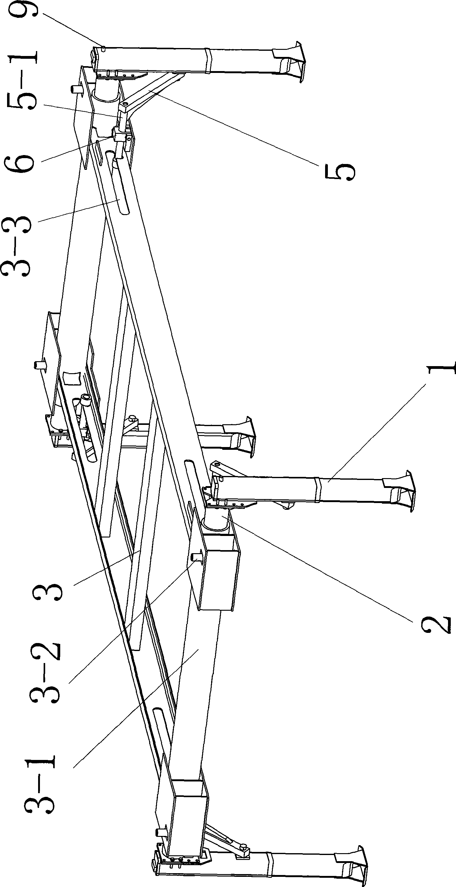
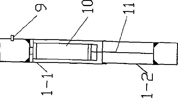
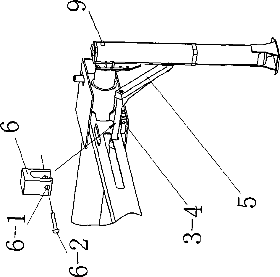
[0018] Such as figure 1 As shown, in the hydraulic lift type tank transportation and loading and unloading rack, there is a load-bearing frame 3 arranged horizontally for bearing the weight of the tank. The four corners of the load-bearing frame are equipped with a vertically arranged support leg 1, and each support leg It is hinged and reinforced with the load-bearing frame by a tendon rod 5 (the reinforcement structure is: one end of the tendon rod 5 is hinged on the support leg, and the other end of the tendon rod 5 is fixed to the horizontal sliding rod 5-1 embedded in the chute on the beam of the load-bearing frame In the positioning opening 3-31 of 3-3, after straddling the horizontal slide bar 5-1 with the gland 6, the pin 6-2 is inserted into the pin hole 6-1 of the gland 6 and the pin hole at the corner end of the load-bearing frame 3-4, the tendon rod 5 is fixed); the load-bearing frame is also provided with a lifting mechanism so that the load-bearing frame can be ...


PUM


Abstract

The invention relates to a special device for a loading and unloading tank of a land vehicle, which aims to provide a device which has the characteristics of firm structure, safe and reliable use, and simple and convenient as well as labor-saving operation. The technical proposal comprises that: a transportation loading and unloading rack of a hydraulic lifting type tank comprises a bearing frame which is used for bearing the weight of the tank, supporting legs arranged on four corners of the bearing frame, a hydraulic lifting mechanism for driving the bearing frame to vertically lift, and a translational mechanism capable of adjusting the horizontal displacement of the supporting legs. The supporting legs comprise two inner cylinders and two outer cylinders which are vertically positioned, mutually sleeved and slide mutually. The hydraulic lifting mechanism comprises that: a cylinder body of an oil cylinder is arranged in an inner cavity of the outer cylinder of the supporting leg, the top end of a piston rod of the oil cylinder extends downward to an inner cavity of the inner cylinder and is fixed with the cylinder bottom of the inner cylinder, the outsides of the cylinder walls of the outer cylinders are provided with oil pipe connectors which are communicated with the cylinder body of the oil cylinder, and an oil pump conveys hydraulic oil through the oil pipe connectors. The translational mechanism comprises that: a sliding shaft fixed at the upper end of each supporting leg is inserted into a proper sleeve; and the sleeves are fixed on the bearing frame.

Description

technical field [0001] The invention relates to a tank loading and unloading device; especially a professional device for land vehicles loading and unloading tanks. Background technique [0002] Tank filling and vehicle transportation are common land transportation methods for liquid materials such as liquefied petroleum gas, gasoline and diesel, and sulfuric acid. At present, the transportation of tanks is mainly dragged by semi-trailer carriages, and the tanks are fixed on specific carriages with supporting legs and wheels, which cannot be easily separated. In this way, each tank needs to be equipped with a special carriage, which not only reduces the vehicle utilization rate, but also takes up more funds and resources, and increases the cost. In addition, the loading and unloading of tanks requires special lifting equipment, which not only requires increased investment, but also affects the efficiency of vehicles due to the failure to complete timely loading and unloadin...

Claims


Application Information

Patent Timeline
Patent Type & Authority Applications(China)
IPC IPC(8): B65G69/00B65D90/12B65D88/12
Inventor 武传宇施响军毛晓捷李秦川张雷胡旭东杨蒙爱
Owner ZHEJIANG SCI-TECH UNIV
Why Eureka
Try Eureka